5-138 T60 Transformer Protection System GE Multilin
5.4 SYSTEM SETUP 5 SETTINGS
5
CONFIGURATION EXAMPLE: CFG-2 BASED CONFIGURATION (USING IEC 61850-90-5)
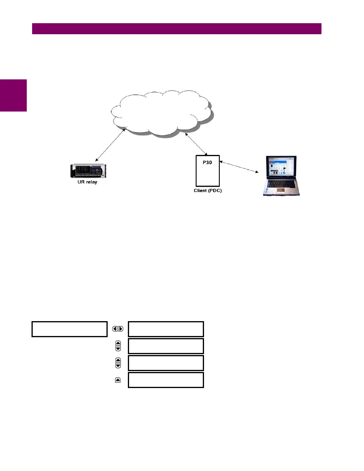
The T60 is expected to send the CFG-2 file (IEEE C37.118 config. file) upon request from the upstream synchrophasor
devices (for example, P30) without stopping R-SV multicasting, as shown in the figure below. The primary domain control-
ler (PDC) does not need to use a stop/start data stream command if the UR protocol is set to IEC 61850-90-5 prior to
requesting the configuration via CFG-2 (IEEE C37.118 config. file). The CFG-2 request from the P30 can be on TCP/IP or
UDP/IP, however, R-SV data streaming is only UDP multicasts (not TCP).
Figure 5–50: CFG-2 BASED CONFIGURATION SOLUTION
MODIFICATION OF SYNC WORD IN CFG-2 FOR TR 90-5 DATA SETS
In the CFG-2 file, all relevant information about the data being streamed is included. However, this file does not include the
fact that it describes a 90-5 dataset or the number of Application Service Data Units (datasets). In order to communicate
this information via the CFG-2 file for a given aggregator, when the aggregator is set to 90-5, the version number of the
CFG-2 file (found in bits 0-3 of the frame SYNC word, which should presently be set to 2) is set as follows:
The PMU settings are organized in logical groups as follows.
PATH: SETTINGS SYSTEM SETUP PHASOR MEASUREMENT UNIT PHASOR MEASUREMENT UNIT 1
VALUE
(DECIMAL)
# OF ASDUS
11 1
12 2
13 3
14 4
PHASOR MEASUREMENT
UNIT 1
PMU 1 BASIC
CONFIGURATION
See page 5-139.
MESSAGE
PMU 1
CALIBRATION
See page 5-143.
MESSAGE
PMU 1
TRIGGERING
See page 5-144.
MESSAGE
PMU 1
RECORDING
See page 5-152.
 Loading...


