4.6 Setting the Screen Display
100
You can select a display color for each logic channel waveform.
You can select the display position of each logic
waveform. Waveform overlap on the display can be
minimized when recording simultaneously with an
analog waveform.
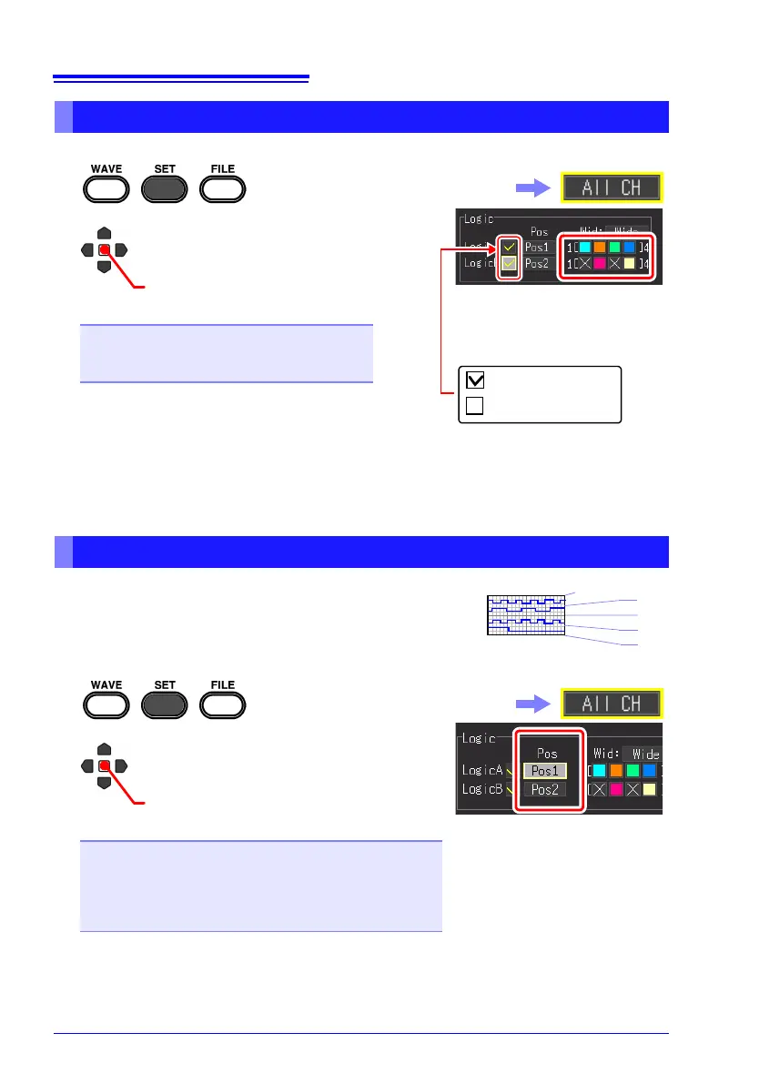
Setting Logic Channel Display Colors
1
2
(Open/confirm the setting information.)
Select from the setting options of
waveform display colors.
Setting options
Off, 1 to 24 colors
The default setting varies depending on the
channel.
The setting can also be changed
on the Waveform screen
([Wave+Set] display) and [CH]
screen.
You can simultaneously turn on
or off the display of four channels
for each logic probe.
: Display On
: Display Off
OFF
Select the [All CH] screen.
Setting Logic Channel Display Positions
1
2
Select from the setting options of
[Pos].
The setting can also be changed
on the Waveform screen
([Wave+Set] display) and [CH]
screen.
Setting options
Pos1, Pos2, Pos3, Pos4
Pos5*, Pos6*, Pos7*, Pos8*
*. This can only be selected when the logic recording width
is [Narrow].
(default setting): LogicA Pos1, LogicB Pos2
(Open/confirm the setting information.)
Select the [All CH] screen.
 Loading...