4.9 Recording Using Specific Conditions (Trigger Function)
119
Chapter 4 Setting the Measurement Conditions (When you want to customize the settings)
4
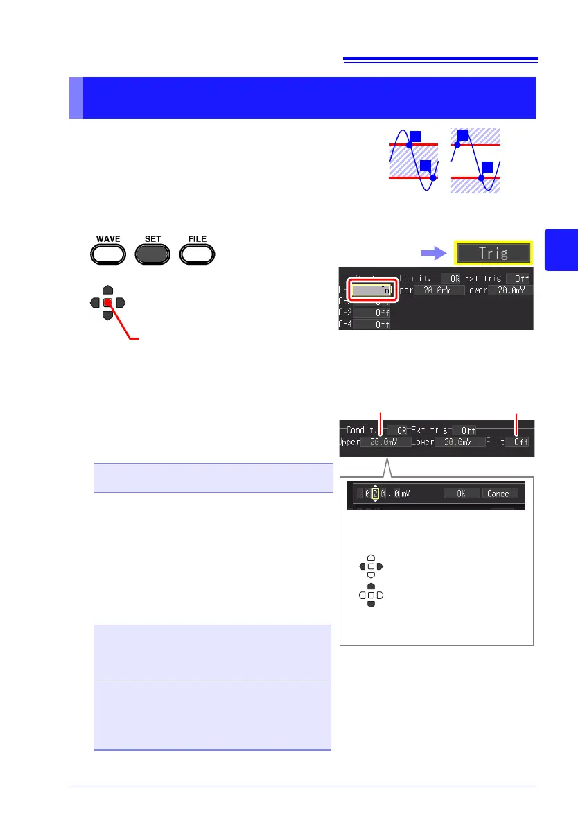
Measurement starts or stops when the input signal
enters (IN) or exits (OUT) a range defined by upper
and lower limit values.
You can check the upper and lower limit values on
the [CH] screen.
This can be set on the [Trig] screen, [CH] screen, and [Wave+Trg] display.
Applying a Trigger Using Range Specified by Upper & Lower
Limit Values (Window Trigger)
1
2
Select [In] or [Out] for the
trigger type.
In the following steps, use the same operation to
configure settings.
(Open/confirm the setting information.)
Select the [Trig] screen.
3 Select from the setting options of
[Upper]/[Lower].
Setting options
4 Set [Filt (filter)].
A trigger is applied when the application condi-
tion of the trigger is met in the period of the set
[Filt (Filter)]. This is effective for preventing in-
correct operation caused by noise. The options
that can be set differ depending on the func
-
tion.
Setting options (∗. default setting)
- vertical axis (voltage axis) range x 10 to
+ vertical axis (voltage axis) range x 10
(When High-speed Function)
Set by number of samples
Off∗, 10S, 20S, 50S, 100S, 200S, 500S, 1000S
(S = Number of samples)
(When Real-time Function)
Off∗, On
(When this is On, the filter width is fixed to 10 ms.)
Note: The filter width is 2 samples when the re-
cording interval is 10 ms or longer.
Set the value for each digit, and then
select [OK] to confirm the setting.
When noise is a concern (p. 118)
3
4
Change 1’s digit and switch
between + and -
Select another digit
 Loading...