4.9 Recording Using Specific Conditions (Trigger Function)
117
Chapter 4 Setting the Measurement Conditions (When you want to customize the settings)
4
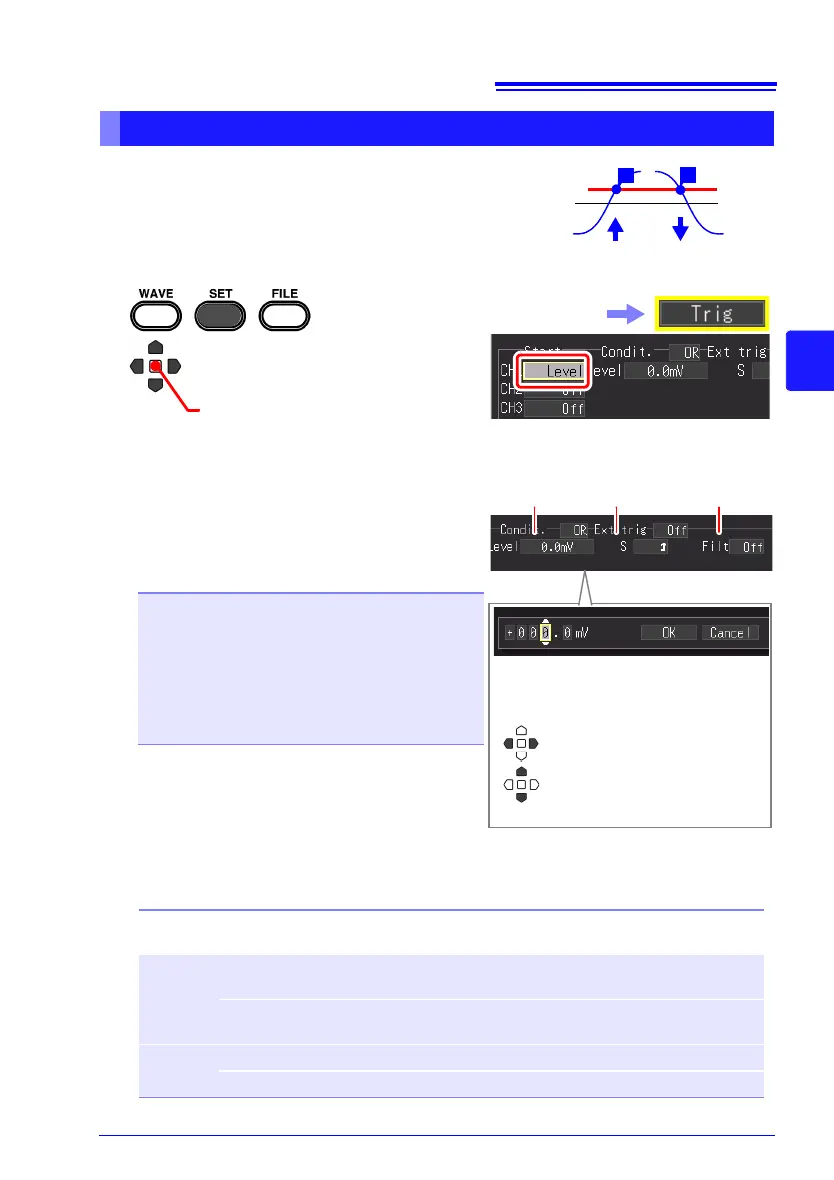
You can specify the desired signal level (level) and
the direction (slope) of change of the input signal in
order to apply a trigger. The options that can be set
differ depending on the function.
This can be set on the [Trig] screen, [CH] screen, and [Wave+Trg] display.
Applying a Trigger at a Specified Value (Level Trigger)
1
2
Select [Level] (level trigger) for
the trigger type.
In the following steps, use the same operation to
configure settings.
This can also be set for each chan-
nel on the [CH] screen.
(Open/confirm the setting information.)
Select the [Trig] screen.
3 Set a numerical value for the signal
level you want to detect in [Level] (sig
-
nal level)
Setting options (default setting: 0 )
4 Select the judgment item for the input
signal from the setting options of [S
(slope)].
The options that can be set differ depending on
the trigger application condition (AND/OR).
Settable range: - (minus) full scale value to +
(plus) full scale value
Full scale value = vertical axis (voltage axis) range
[V/div] x 10 div
Example: When the vertical axis (voltage axis)
range is 20 V/div:
20 V/div x 10 div = 200 V
200 V becomes the full scale value.
3
4
Set the value for each digit, and then
select [OK] to confirm the setting.
Setting options (∗. default setting)
Trigger
Condition
Selec-
tion
Description of Operation
OR ↑ A trigger is applied when the input signal crosses the trigger level in the
up direction ().
↓ A trigger is applied when the input signal crosses the trigger level in the
down direction ().
AND HIGH A trigger is applied when the input signal rises above the trigger level.
LOW A trigger is applied when the input signal falls below the trigger level.
5
Change 1’s digit and
switch between + and -
Select another digit
 Loading...