4.4 Using Real-time Function (Fluctuation Recording)
79
Chapter 4 Setting the Measurement Conditions (When you want to customize the settings)
4
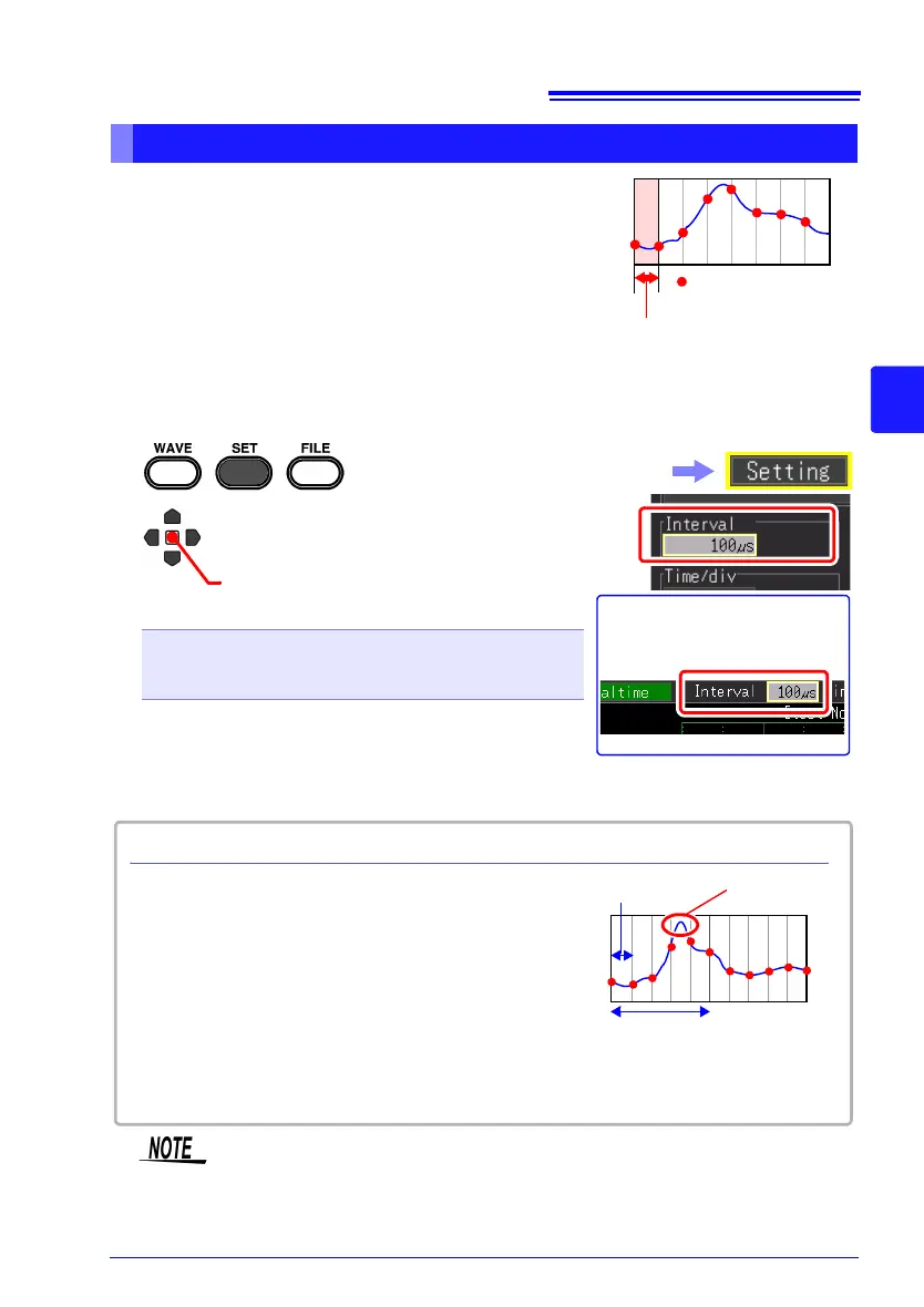
Set the interval for acquiring data
Select the data acquisition interval to suit your mea-
surement objectives.
If a short recording interval is selected, the recording
time for which data can be stored in the internal buffer
memory will be short. If you want to retain the data for a
long period of time, we recommend setting continuous
recording to [On] and saving in real time to external storage media.
Setting the Interval for the Data to Record (Recording Interval)
: Measurement data
Recording interval
1
2
(Open/confirm the setting information.)
Select from the setting options of
[Interval].
Setting options (∗. default setting)
100μs∗, 200μs, 500μs,
1ms, 2ms, 5ms, 10ms, 20ms, 50ms, 100ms, 200ms,
500ms, 1s, 2s, 5s, 10s, 20s, 30s, 1min
The setting can also be
changed on the Waveform
screen. ([Wave+Set] Display)
Select the [Setting] screen.
Some waveform peaks may not be displayable
with certain interval settings.
Example: When the recording interval is set to 1
s and the horizontal axis is set to 5 s/div, a state
in which the waveform peak cannot be recorded
is displayed.
To make sure the peak is recorded:
"Retaining Records of Maximum and Minimum
Values (Envelope)" (p. 84)
Recording Interval and Waveform Peak
Horizontal axis: 5 s/div
Recording interval: 1s
Peak
If real time saving, [Envelope] function, and [Numerical Calc.] are set at
the same time, the recording interval cannot be set to 100 µs and 200
µs.
 Loading...