The relation between each trigger source can be set. This is only valid for channels
1
2
(Open/confirm the setting information.)
Select the relation between trigger
sources from the setting options of
[Condit.].
Setting options (∗. default setting)
OR∗
A trigger is applied at the change point (edge)
when any one of the set trigger conditions chang-
es from an unmet state to a met state. Therefore,
even if a trigger condition is met at the start point
in time, the trigger is not applied until the change
point is detected.
Note: The "change point" indicates the point
when the trigger condition changes from an un-
met state to a met state.
AND A trigger is applied when all of the set trigger con-
ditions are met. Therefore, if the trigger condi-
tions are met at the start point in time, the trigger
is applied immediately.
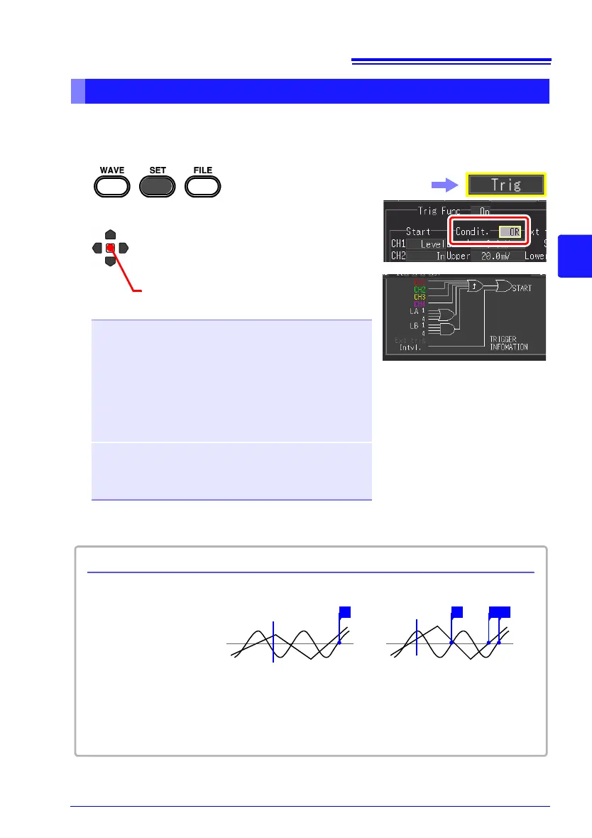
You can confirm the trigger appli-
cation conditions between chan-
nels on the screen.
Select the [Trig] screen.
[AND]
One waveform has crossed
above 0 V as the other crosses
on the upslope
[OR]
Either waveform crosses 0 V on
the upslope
Start measurement
Trigger .......Level
Level .............0 V
Slope..................↑
(Example) To apply a trigger when the upslope (↑) of the waveform crosses zero volts:
Start
measurement
T T T T
About Trigger Application Conditions
0 V 0 V
 Loading...