Details
For detecng a pulse train, the following two conguraons are supported:
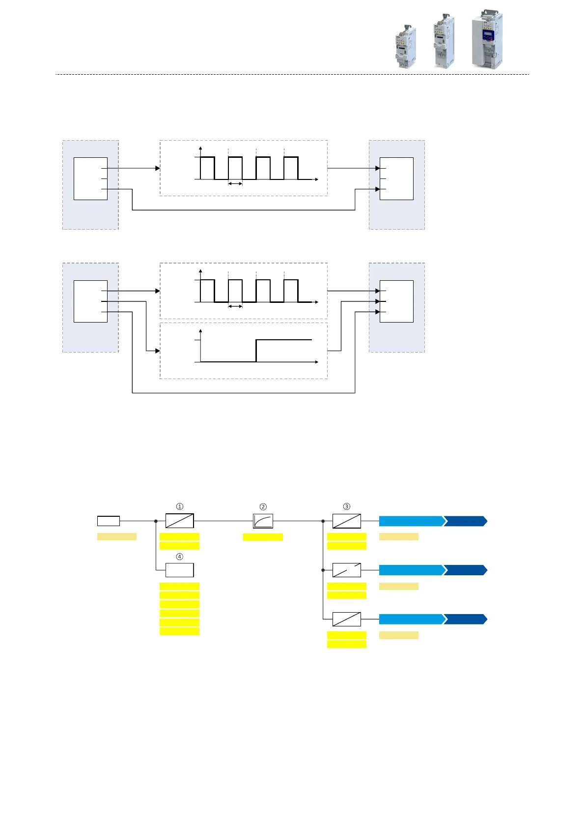
a)
input funcon 0x2630:002 (P410.02) = "Pulse train [2]"
(DI4 = input for pulse train, DI3 = normal digital input)
Controller
PTO1
PTO2
COM
Inverter
DI4
DI3
GND
X3
VDC
Pulse 4Pulse 1 Pulse 2 Pulse 3
Duty cycle (30 ... 70 %)
15 ... 24
0
t
b)
input funcon 0x2630:002 (P410.02) = "Pulse train/direcon [3]"
(DI4 = input for pulse train, DI3 = input for specicaon of direcon)
Controller
PTO1
PTO2
COM
Inverter
DI4
DI3
GND
X3
VDC
Pulse 4Pulse 1 Pulse 2 Pulse 3
Duty cycle (30 ... 70 %)
15 ... 24
0
t
LOW = FWD (CW)
HIGH = REV (CCW)
VDC
15 ... 24
0
t
For detecng an HTL encoder AB signal, the input funcon "HTL encoder (AB) [1]" must be set
in 0x2630:002 (P410.02) instead. More details for conguring the HTL encoder can be found in
chapter "HTL encoder". ^ 496
The following sengs are possible for the HTL input:
•
Denion of the input range
①
•
Filter me for low-pass lters
②
•
Denion of the seng range
③
•
Monitoring of the input signal
④
DI4
0x2640:0030x2640:001
%
Hz
0x2640:009
0x2640:004
0x2640:005
0x2640:006
%
PID
X3
%
Hz
0x2642:002
0x2642:003
0x2860:001
0x2860:002
[Hz]
[PID unit]
0x2640:007
0x2640:008
%
%
0x2642:004
0x2860:003
[%]
unit
0x2641:001
0x2641:002
0x2641:003
0x2641:004
0x2641:005
0x2641:006
0x2642:001
0x2640:002
[Hz]
f x Hz
<
>
HTL input [4]
Torque setpoint source
HTL input [4]
Process controller setpoint source
Frequency setpoint source
HTL input [4]
Diagnosc parameters:
•
The input frequency is displayed in 0x2642:001 (P115.01).
•
The scaled frequency value is displayed in 0x2642:002 (P115.02).
•
The scaled process controller value is displayed in 0x2642:003 (P115.03).
•
The scaled torque value is displayed in 0x2642:004 (P115.04).
Flexible I/O conguraon
Setpoint change-over
HTL input setpoint source
566
 Loading...


