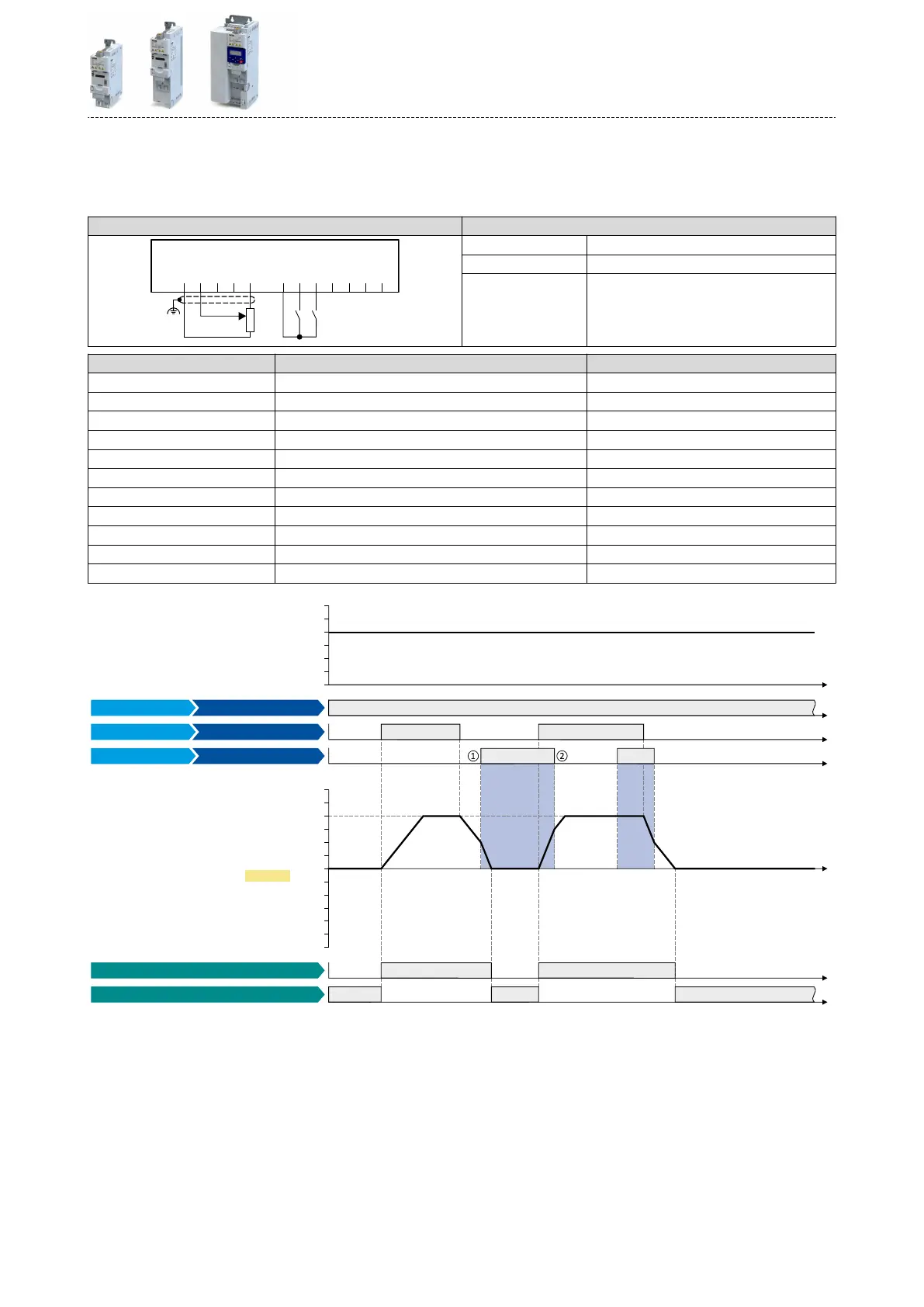
Example for operang mode
•
Switch S1 starts the motor in forward direcon of rotaon. Switch S1 in the inial posion
stops the motor again.
•
Switch S2 acvates the acceleraon me 2 and deceleraon me 2.
Connecon plan funcon
GND
AI1
AI2
AO1
10V
24V
DI1
DI2
DI3
DI4
DI5
DO1
X3
S1 S2
1k ...10k
0 ... 10 V
R1
Potenometer R1 Frequency setpoint selecon
Switch S1 Run
Switch S2 Acvate ramp 2
Parameter Name Seng for this example
0x2631:001 (P400.01) Enable inverter Constant TRUE [1]
0x2631:002 (P400.02) Run Digital input 1 [11]
0x2631:004 (P400.04) Reset fault Not connected [0]
0x2631:039 (P400.39) Acvate ramp 2 Digital input 2 [12]
0x2824 (P200.00) Control selecon Flexible I/O conguraon [0]
0x2838:003 (P203.03) Stop method Standard ramp [1]
0x2860:001 (P201.01) Frequency control: Default setpoint source Analog input 1 [2]
0x2917 (P220.00) Acceleraon me 1 10.0 s
0x2918 (P221.00) Deceleraon me 1 10.0 s
0x2919 (P222.00) Acceleraon me 2 5.0 s
0x291A (P223.00) Deceleraon me 2 5.0 s
t
t
t
0 Hz
30 Hz
10 Hz
20 Hz
40 Hz
50 Hz
60 Hz
0 Hz
30 Hz
10 Hz
20 Hz
40 Hz
50 Hz
60 Hz
-40 Hz
-60 Hz
-50 Hz
-30 Hz
-20 Hz
-10 Hz
t
t
t
t
0x2DDD
Running [50]
Stop active [53]
Constant TRUE [1]
Digital input 1 [11]
Digital input 2 [12]
Output signals
Status signals
Output frequency
Activate ramp 2
Run
Inverter enable
Input signals
Frequency setpoint selection
FunctionTrigger
The status signals can be assigned to digital outputs. 4Conguraon of digital outputs ^ 603
①
Change-over to deceleraon me 2 during the deceleraon phase.
②
Change-over to acceleraon me 1 during the acceleraon phase.
Flexible I/O conguraon
Acvang ramp 2 manually
577
 Loading...


