10 Input Wiring Procedures
10.6 Pulse width/Pulse period measurement function
129
FX3G Series Programmable Controllers
User's Manual - Hardware Edition
1
Introduction
2
Features and
Part Names
3
Product
Introduction
4
Specifications
5
Version and
Peripheral
Devices
6
System
Configuration
7
Input/Output
Nos., Unit Nos.
8
Installation
9
Preparation and
Power Supply
Wiring
10
Input Wiring
10.6 Pulse width/Pulse period measurement function
(Supported in Ver. 1.10 or later)
Four input points in the PLC (main unit) can be used for the pulse width/period measurement function which
enables measurement of the pulse width or pulse frequency in units of 10 s.
→ For details on programming, refer to the programming manual.
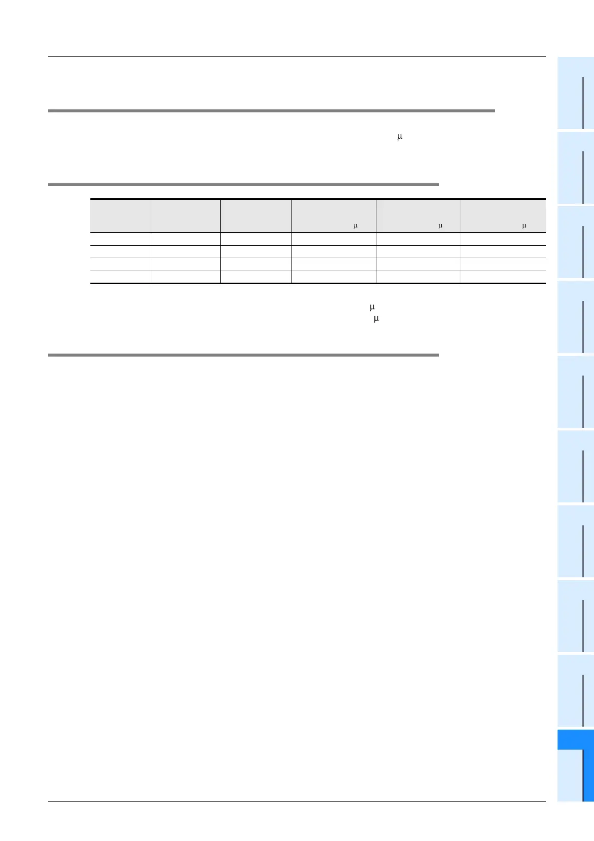
10.6.1 Allocation of special memories to input numbers
*1. Cleared when PLC switches from STOP to RUN.
*2. The pulse width which can be measured is a minimum of 10 s and a maximum of 100s.
The pulse period which can be measured is a minimum of 20 s.
10.6.2 Cautions for pulse width/period measurement function
1. Non-overlap of input numbers
The input terminals X000, X001, X003 and X004 can be used for high-speed counter, input interruption, pulse
catch, speed detection (SPD) instructions and general-purpose input.
Take care not to overlap the input numbers.
However, overlap of input numbers is allowed for input interruptions.
Example:
When the pulse width/period measurement flag M8076 is used, X000 is occupied. Therefore, it is impossible
to use C235, C241, C244, C246, C247, C249, C252 and C254, pulse catch contact M8170, SPD, ZRN and
DSZR instructions at the same time.
2. When the pulse width/period measurement function and high-speed counters are used
together, the overall frequency of high-speed counters is affected.
→ For more details, refer to Section 11.7.
3. Make sure that the total frequency of four input channels is 50kHz or less when using the
pulse width/period measurement function.
→ For details on programming, refer to the programming manual.
Input number
Pulse width/
Pulse period
measurement flag
Pulse period
measurement
mode
Ring counter value for
rising edge
*1
[in units of 1/6 s]
Ring counter value for
falling edge
*1
[in units of 1/6 s]
Pulse width/
Pulse period
*1*2
(in units of 10 s)
X000 M8076 M8080 D8075, D8074 D8077, D8076 D8079, D8078
X001 M8077 M8081 D8081, D8080 D8083, D8082 D8085, D8084
X003 M8078 M8082 D8087, D8086 D8089, D8088 D8091, D8090
X004 M8079 M8083 D8093, D8092 D8095, D8094 D8097, D8096
 Loading...


