14 Test Operation, Adjustment, Maintenance and Troubleshooting
14.3 Operation and Test [Power ON and PLC Running]
171
FX3G Series Programmable Controllers
User's Manual - Hardware Edition
11
High-Speed
Counters
12
Output Wiring
13
Wiring for
Various Uses
14
Test Run,
Maintenance,
Troubleshooting
15
Input/Output
Powered
Extension Units
16
Input/Output
Extension
Blocks
17
Extension
Power Supply
Unit
18
Other Extension
Units and
Options
19
Display Module
20
Terminal Block
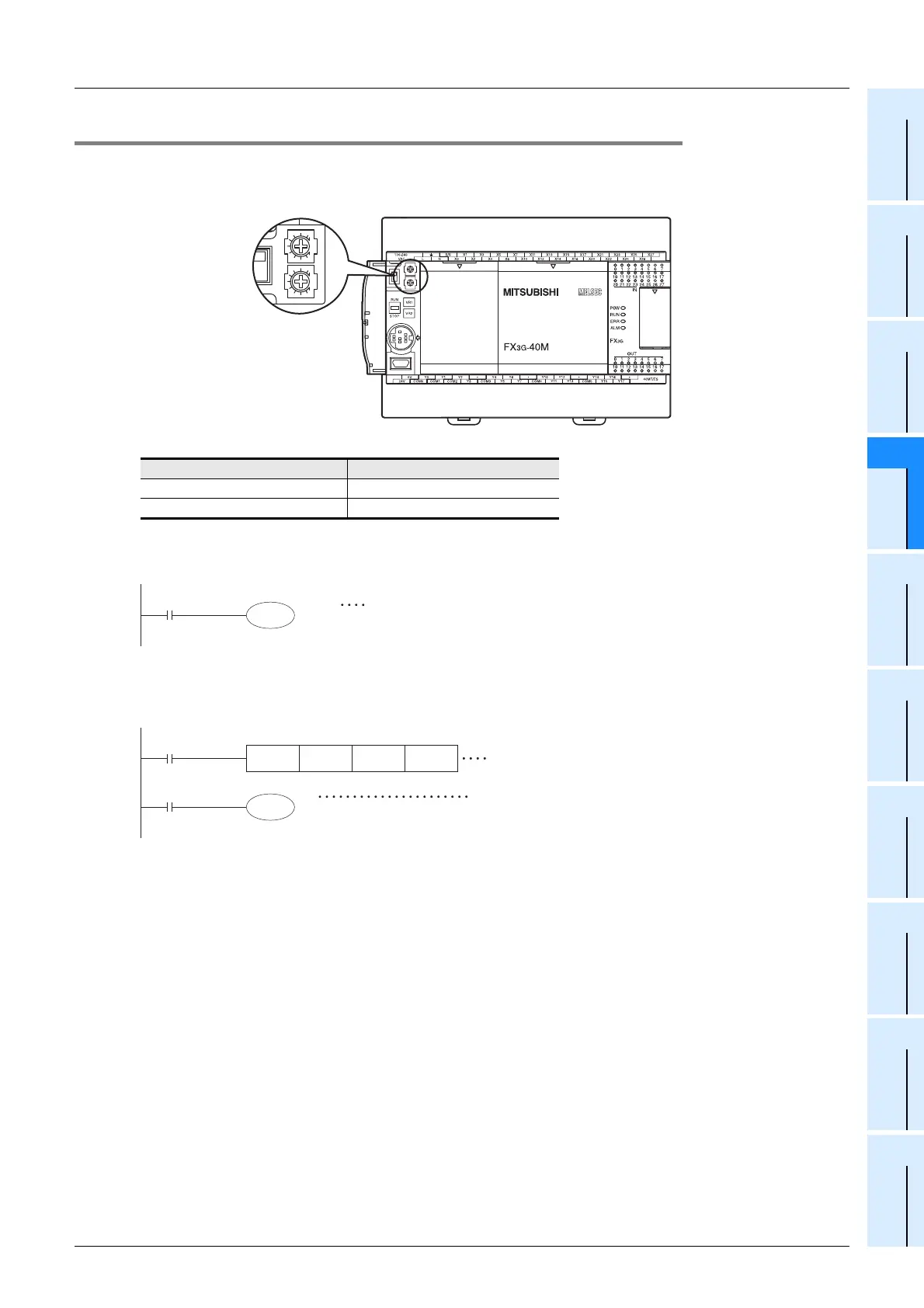
14.3.4 Built-in variable analog potentiometer function
The main unit has two built-in variable analog potentiometers (shown in the figure below).
The current value increases from 0 to 255 when a variable analog potentiometer is turned clockwise.
The current value of each variable analog potentiometer is stored in special data registers shown below.
1. Use example 1 of variable analog potentiometer
The current value of VR1 is used as the set value of a timer.
2. Use example 2 of variable analog potentiometer
The current value of VR2 multiplied by "10" is used as the set value of a timer.
Volume Data register to store current value
VR1 : variable analog potentiometer1 D8030 (Integer from 0 to 255)
VR2 : variable analog potentiometer2 D8031 (Integer from 0 to 255)
Enlarged view
D8030
T0
The current value of VR1 is used as the set value of the timer T0.
The setting range in this example using T0 (100ms timer) is from 0 to
25.5 sec.
D0 The current value of VR2 multiplied by "10" is used as the
set value of the timer T1.
The setting range in this example using T1 (100ms timer)
is from 0 to 255 sec.
MUL
M8000
T1
D8031 K10 D0
The value of D8031 is multiplied by "10", and stored in
D0.

 Loading...


