13 Examples of Wiring for Various Uses
13.1 Notes about Examples of Wiring
154
FX3G Series Programmable Controllers
User's Manual - Hardware Edition
13.1 Notes about Examples of Wiring
The examples of wiring are given under the following conditions.
→ For the example of positioning wiring, refer to the Positioning Control Edition.
• The input/output numbers are the actual numbers on the program. (They may differ from the numbers
shown on the product terminals.)
• Product input/output specifications
Check the product input/output specifications when using any example of wiring.
- Products only for sink input and products both for sink input and for source input are available.
• The examples of programming (applied instructions) are given based on the allocation of the input/output
numbers for wiring.
→ For the applied instructions, refer to the Programming Manual.
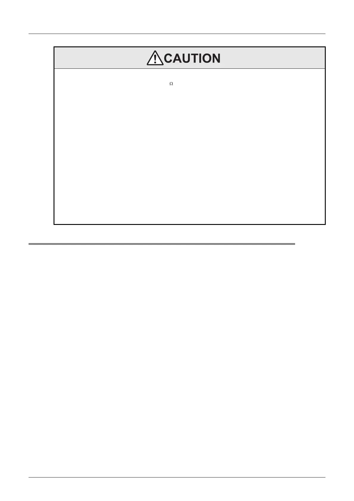
WIRING PRECAUTIONS
• Do not supply power to the [24+] and [24V] terminals (24V DC service power supply) on the main unit or extension units.
Doing so may cause damage to the product.
• Perform class D grounding (grounding resistance: 100 or less) to the grounding terminal on the main unit and extension units with a
wire 2 mm
2
or thicker.
Do not use common grounding with heavy electrical systems (refer to Section 9.3).
• Do not wire vacant terminals externally.
Doing so may damage the product.
• Connect the DC power supply to the dedicated terminals specified in this manual.
If an AC power supply is connected to a DC input/output terminal or DC power supply terminal, the PLC will burn out.
• When drilling screw holes or wiring, make sure cutting or wire debris does not enter the ventilation slits.
Failure to do so may cause fire, equipment failures or malfunctions.
• Make sure to properly wire the FX2N/FX3U Series extension equipment in accordance with the following precautions.
Failure to do so may cause electric shock, a short-circuit, wire breakage, or damage to the product.
- The disposal size of the cable end should follow the dimensions described in this manual.
- Tightening torque should be between 0.5 and 0.8 N•m.
• Make sure to properly wire to the European terminal board in accordance with the following precautions.
Failure to do so may cause electric shock, a short-circuit, wire breakage, or damage to the product.
- The disposal size of the cable end should follow the dimensions described in this manual.
- Tightening torque should be between 0.22 and 0.25 N•m.
- Twist the end of strand wire and make sure that there are no loose wires.
- Do not solder-plate the electric wire ends.
- Do not connect more than the specified number of wires or electric wires of unspecified size.
- Affix the electric wires so that neither the terminal block nor the connected parts are directly stressed.
• Make sure to properly wire to the FX Series terminal blocks in accordance with the following precautions.
Failure to do so may cause electric shock, a short-circuit, wire breakage, or damage to the product.
- The disposal size of the cable end should follow the dimensions described in this manual.
- Tightening torque should be between 0.5 and 0.8 N•m.
 Loading...


