8 Installation In Enclosure
8.4 Procedures for Installing on and Detaching from DIN Rail
91
FX3G Series Programmable Controllers
User's Manual - Hardware Edition
1
Introduction
2
Features and
Part Names
3
Product
Introduction
4
Specifications
5
Version and
Peripheral
Devices
6
System
Configuration
7
Input/Output
Nos., Unit Nos.
8
Installation
9
Preparation and
Power Supply
Wiring
10
Input Wiring
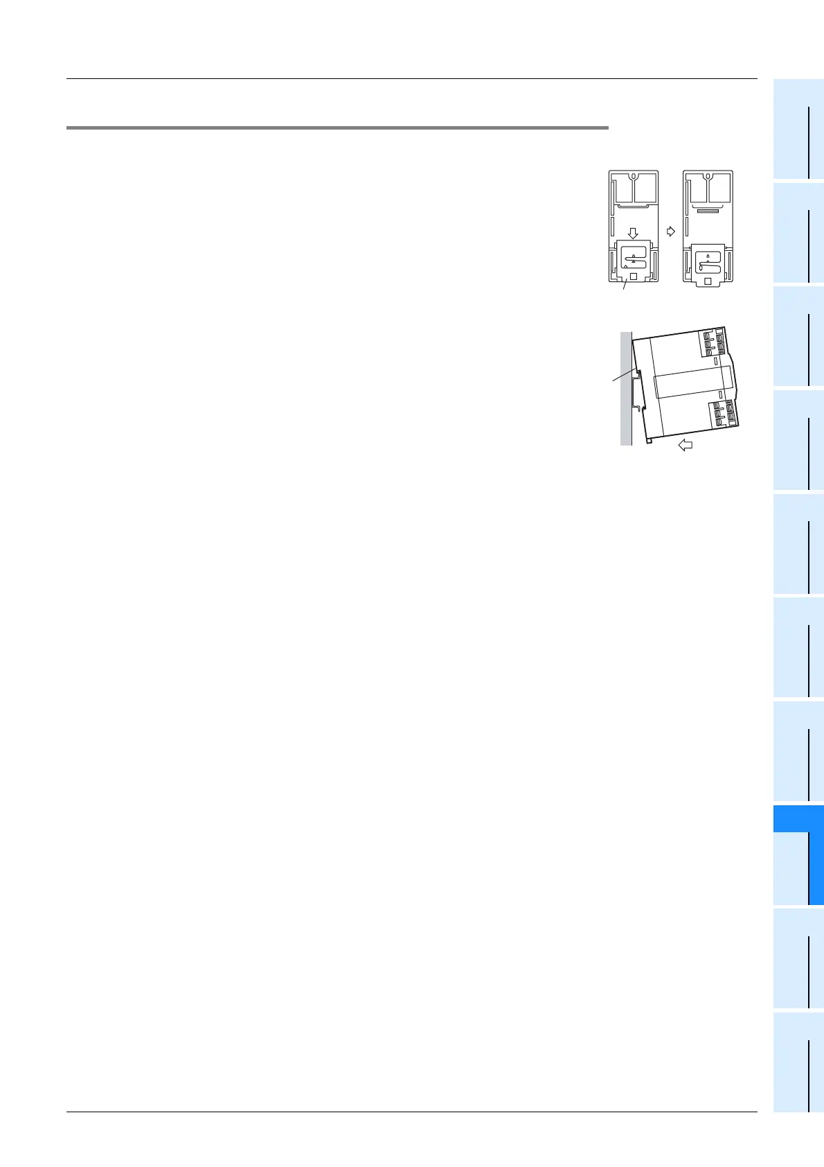
8.4.3 Installation of input/output powered extension unit/block and special function block
1 Push out the DIN rail mounting hook (A in the right fig-
ure) of the input/output extension block.
• For input/output powered extension units, 8-point type input/output
extension blocks and special extension units/blocks, this operation is
unnecessary.
2 Fit the upper edge of the DIN rail mounting groove (B
in the right figure) onto the DIN rail.
3 Push the product against the DIN rail.
• Keep a gap of 1 to 2 mm (0.04" to 0.08") between the products.
4 Connect the extension cable.
→ For the procedures on connecting the extension cable, refer to Subsection 8.6.5.
Rear panel Rear panel
A
1
B
3
 Loading...


