Clocks and Power Control
5-12
MPC823e REFERENCE MANUAL
MOTOROLA
CLOCKS AND POWER
5
CONTROL
5.3.1 On-Chip Oscillators and External Clock Input
The main clock oscillator (OSCM) uses either a 3-5MHz source at EXTCLK (4MHz mode)
oscillator or a 30-50kHz (32kHz mode) crystal between EXTAL and XTAL to generate the
SPLL reference clock (OSSCLK). The external clock input EXTCLK is generated from an
external source. In one-to-one mode, the input clock frequency must be at least 15MHz.
Otherwise, it can be between 3 and 5MHz. See Figure 5-1 for details.
For normal operation, at least one clock source must be active, but it is possible to configure
both clock sources to be active. When both clock sources are active, the EXTCLK pin
provides the OSCCLK signal for the SPLL. The EXTAL and XTAL pins provide the input
frequency for the OSCM that generates the PITRTCLK signal. The input of an unused timing
reference must be grounded.
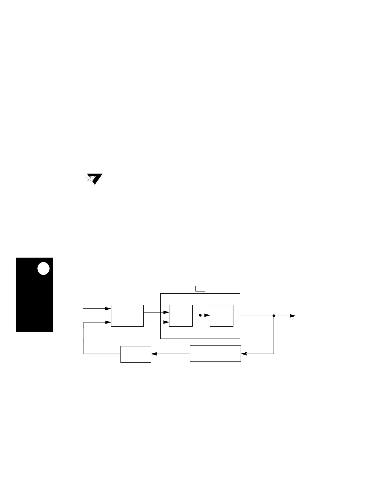
5.3.2 System PLL
The main purpose of the SPLL is to generate a stable reference frequency by multiplying
the frequency and eliminating the clock skew. The SPLL allows the processor to operate at
a high internal clock frequency using a low frequency clock input, which gives you two
advantages. Lower frequency clock input reduces the overall electromagnetic interference
generated by the system. Also, oscillating at different frequencies reduces the cost because
you will not have to add more oscillators to your system. The MPC823e SPLL block diagram
is illustrated in Figure 5-4.
Note:
Under any condition, the voltage on the MODCK1 and MODCK2 pins must be
less than or equal to the power supply voltage VDDH applied to the part.
Figure 5-4. SPLL Block Diagram
VDDSYN / VSSSYN
PHASE
COMPARATOR
MULTIPLICATION FACTOR
MF[0:11]
XFC
OSCCLK
UP
DOWN
VCOOUT
FEEDBACK
CLOCK
DELAY
CHARGE
PUMP
VCO
 Loading...