External Bus Interface
MOTOROLA
MPC823e REFERENCE MANUAL
13-3
EXTERNAL BUS
13
INTERFACE
13.2.1 Control Signals
The MPC823e initiates a bus cycle by driving the address, size, address type, cycle type,
and read/write outputs. At the beginning of a bus cycle, the TSIZ0 and TSIZ1 signals are
driven with the AT signals. TSIZx indicates the number of bytes to be transferred during an
operand cycle that consists of one or more bus cycles. These signals are valid at the rising
edge of the clock in which the TS
signal is asserted. The RD/WR signal determines the
direction of the transfer during a bus cycle. Driven at the beginning of a bus cycle, RD/WR
is valid at the rising edge of the clock in which the TS signal is asserted. However, RD/WR
only transitions when a write cycle is preceded by a read cycle or vice versa. The signal may
remain low for consecutive write cycles.
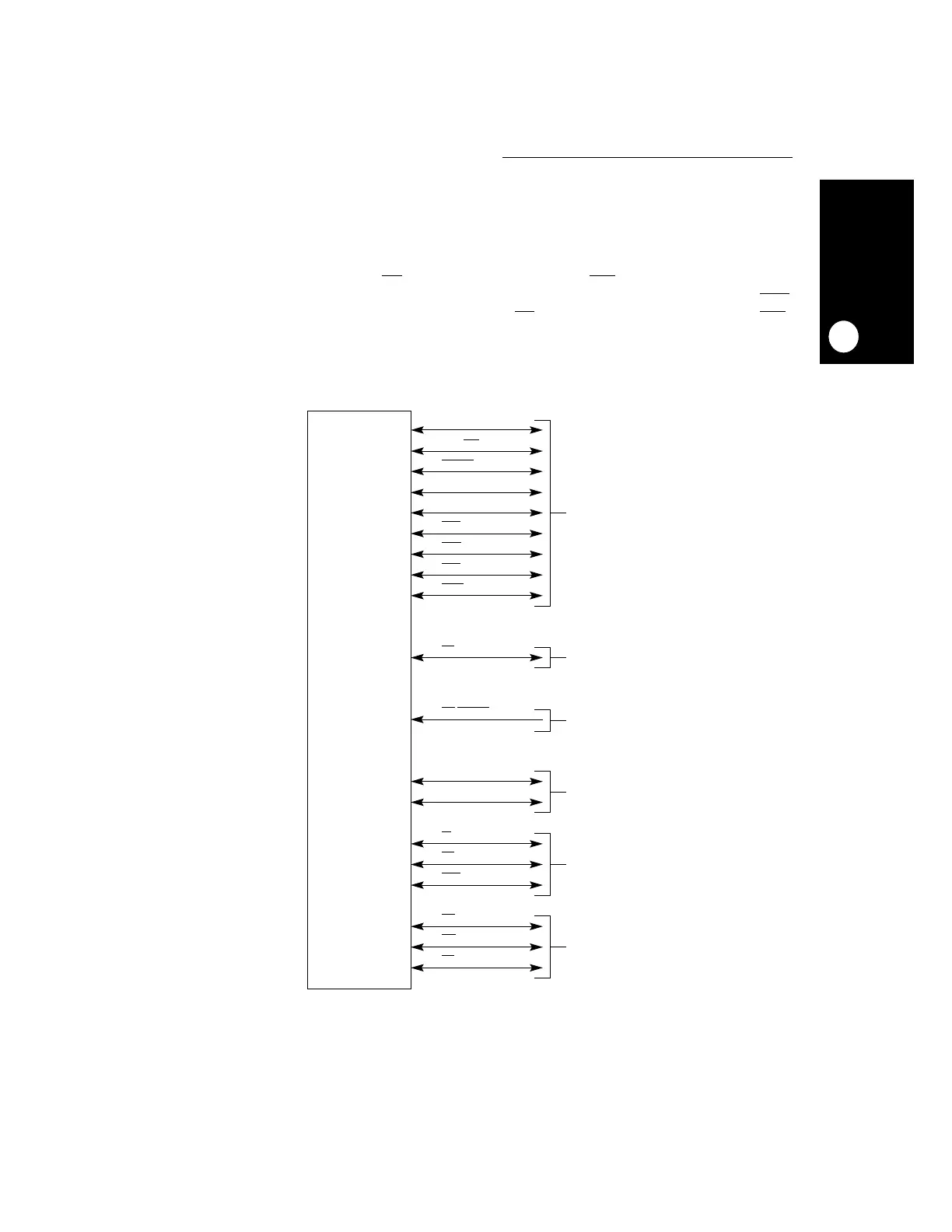
Figure 13-2. MPC823e Bus Signals
A[6:31]
RD / WR
BURST
TSIZ[0:1]
AT[0:3]
STS
TS
BI
KR/RETRY
D[0:31]
TA
TEA
BDIP
DP[0:3]
BR
BG
BB
26
1
1
2
4
1
1
1
1
32
1
1
4
1
1
1
1
ADDRESS
AND
TRANSFER
ATTRIBUTES
TRANSFER
START
ARBITRATION
DATA
TRANSFER
TERMINATION
RESERVATION
PROTOCOL
CYCLE
RSV
1
PTR
1
 Loading...