Clocks and Power Control
5-26
MPC823e REFERENCE MANUAL
MOTOROLA
CLOCKS AND POWER
5
CONTROL
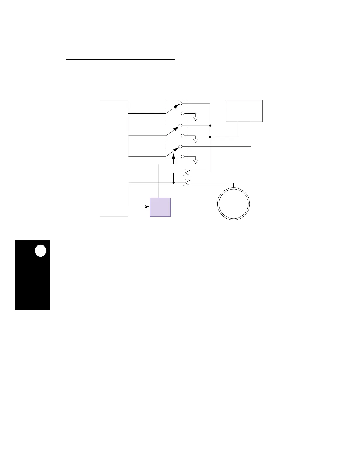
5.4.2.1 POWER SWITCHING EXAMPLE.
An example of a switching scheme for an
optimized low-power system is illustrated in Figure 5-16.
Switch 1 and 2 (SW1 and SW2) can be combined into a single switch if VDDSYN and VDDH
are supplied by the same source. If VDDL is fed with 3.3V, SW2 and SW3 can be combined
into one switch. The TEXP pin, if enabled, is asserted by the MPC823e when the real-time
clock or timebase time value matches the value programmed in its associated alarm register
or when the periodic interrupt timer or decrementer decrements their value to zero. The
TEXP pin is negated when you write a 1 to the TEXPS bit in the PLPRCR.
If the voltage to the KAPWR rises too slow, the OSCM (supplied by KAPWR) will take longer
to stabilize the OSCCLK. The maximum KAPWR rise time must be less than 1.7V/ms for a
32kHz input frequency.
MPC823e
Figure 5-16. External Power Supply Scheme
MAIN POWER
BACKUP
VDDSYN
3.3V 2.2V
VDDH
VDDL
KAPWR
SUPPLY
SWITCH
LOGIC
TEXP
2.5-3.3V
SW1
SW2
POWER
SUPPLY
SW3
 Loading...