System Interface Unit
MOTOROLA MPC823e REFERENCE MANUAL 12-17
SYSTEM INTERFACE UNIT
12
Bits 10–11—Reserved
These bits are reserved and must be set to 0.
REFAE and REFBE—Reference Interrupt Enable
If one of these bits is asserted, the timebase generates an interrupt on assertion of the REFA
or REFB bit. Otherwise, the interrupt is disabled.
TBF—Timebase Freeze Enable
0 = The timebase and decrementer are unaffected.
1 = The FRZ signal stops the timebase and decrementer.
TBE—Timebase Enable
0 = Disables timebase and decrementer operation.
1 = Enables timebase and decrementer operation.
12.7 THE REAL-TIME CLOCK
The real-time clock is a 45-bit counter that is clocked by the PITRTCLK clock. It is used to
provide time-of-day indication to the operating system and application software. The counter
is not affected by reset and operates in all low-power modes. It is initialized by the software.
The real-time clock can be programmed to generate a maskable interrupt when the time
value matches the value programmed in the alarm register. It can also be programmed to
generate an interrupt once every second. A control and status register is used to enable or
disable the different functions and report the interrupt source. The real-time clock
registers—RTCSC, RTC, RTSEC, and RTCAL—are protected (“locked”) from accidental
writes after PORESET
. To unlock the registers, you must write a key word (0x55CCAA33)
to the RTCK register. Refer to Section 5.4.2 Keep-Alive Power for more information.
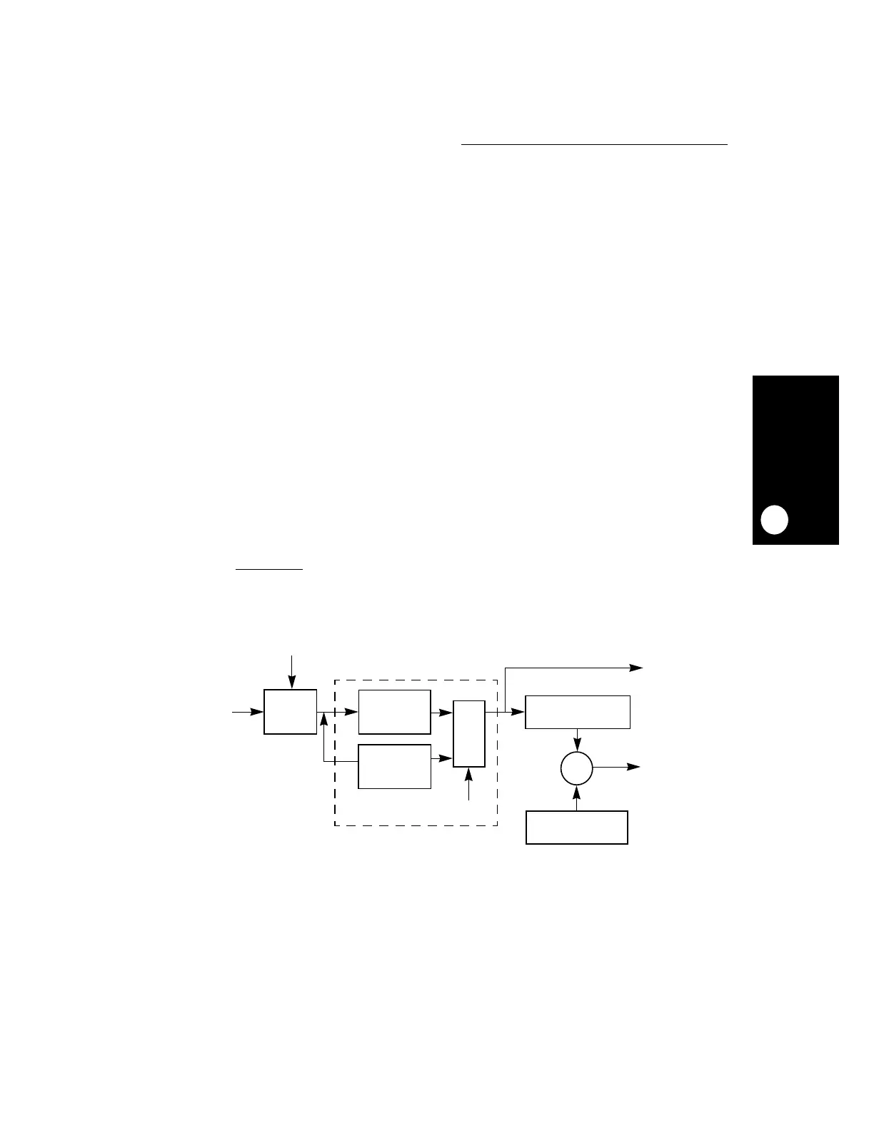
Figure 12-4. Real-Time Clock Block Diagram
PITRTCLK
FRZ
DIVIDE
32-BIT COUNTER
32-BIT REGISTER
SEC
ALARM
=
CLOCK
DISABLE
DIVIDE
MUX
38K
INTERRUPT
INTERRUPT
BY 9,600
BY 8,192
CLOCK
RTSEC
 Loading...