Clocks and Power Control
MOTOROLA
MPC823e REFERENCE MANUAL
5-23
CLOCKS AND POWER
5
CONTROL
5.3.5.2 THE SYSTEM PHASE-LOCKED LOOP PINS.
The internal frequency of the
MPC823e and the output of the CLKOUT pin depends on the quality of the crystal circuit and
the MF bit in the PLPRCR. The SPLL contains the following dedicated pins that are isolated
from common power and ground.
• VDDSYN—The power supply pin for the analog SPLL circuitry. You must provide a
well-regulated voltage to this pin via an extremely low impedance path to the VDD
power rail. The SPLL power plane must be isolated from the VDD power plane with an
LC filter, which gives you the best performance. A 0.1
µ
F bypass capacitor must
connect VDDSYN and VSSSYN and be as close to the chip as possible. To reduce the
noise from the open EXTAL pin, pull it to ground when you are not using it.
• VSSSYN—A ground reference pin for the analog SPLL circuitry. You must provide a
low impedance path from VSSSYN to the ground plane.
• VSSSYN1—A ground reference pin for the analog SPLL circuitry. You must provide a
low impedance path from VSSSYN1 to the ground plane.
• XFC—The external filter capacitor pin that connects to the off-chip capacitor for the
SPLL filter. One terminal of the capacitor is connected to XFC while the other terminal
is connected to the VDDSYN pin. For proper SPLL operation, you must supply a
minimum parallel parasitic resistance value of 30M
Ω
. The value of the XFC capacitor is
based on the value of the MF field in the PLPRCR.
Note:
The Multiply Factor Range is the true multiply factor starting from 1, not 0. If you look at Table 5-4 , it indicates the
“Multiply Factor RANGE”, not the “MF FIELD”, of the PLPRCR. The Multiply Factor (MF) referred to in this table
is the value of the MF field in the PLPRCR plus 1 (or PLPRCRMF + 1). The Multiply Factor (PLPRCRMF + 1) is
the value that should be used in the equations to determine the XFC Capacitor Value.
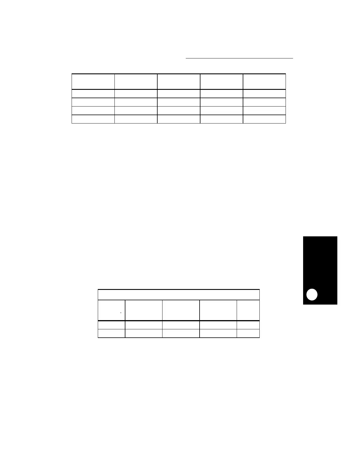
Table 5-3. TMBCLK Dividers
TBS BIT IN SCCR MODCK1 AT
RESET
MF + 1 CLOCK SOURCE TMBCLK DIVISION
1 — — GCLK2 16
0 0 — OSCM 4
0 1 1, 2 EXTAL 16
0 1 > 2 EXTAL 4
Table 5-4. XFC Capacitor Values Based on the MF Field
XFC CAPACITOR VALUES
MULTIPLY
FACTOR
RANGE
MINIMUM
CAPACITANCE
RECOMMENDED
CAPACITANCE
MAXIMUM
CAPACITANCE UNIT
MF
≤
4 (580 *MF) - 100 (680 * MF) - 120 (780 * MF) - 140 pF
MF > 4 830 * MF 1100 * MF 1470 * MF pF
 Loading...