Clocks and Power Control
MOTOROLA
MPC823e REFERENCE MANUAL
5-13
CLOCKS AND POWER
5
CONTROL
The OSCCLK signal goes to the phase comparator that controls the direction in which the
charge pump drives the voltage across the external filter capacitor (XFC). Direction is based
on whether the feedback signal phase lags or leads the reference signal. The output of the
charge pump drives the VCO whose output frequency at VCOOUT is divided down and fed
back to the phase comparator to be compared with the reference frequency (OSCCLK
signal). The multiplication factor must be between 1 and 4,096. Also, when the SPLL is
operating in one-to-one mode, the multiplication factor is 1 (the MF field equals 0).
At the initial system power-up after keep-alive power is lost, external logic must assert the
PORESET
pin for 3µs after a valid level is reached on the keep-alive power supply. When
power-on reset is asserted, the MF field is set as shown in Table 5-1 and the DFNH and
DFNL fields are both set to 0. This MF field value then programs the SPLL to generate the
approximate default system frequency of 16.7MHz when a 32kHz input frequency is used
and 20MHz when a 4MHz input frequency is used.
5.3.2.1 SPLL STABILITY.
The SPLL can multiply the input frequency by any integer that is
between 1 and 4,096. The multiplication factor can be changed by modifying the value of
the MF field in the PLPRCR. Even though any multiplication factor between 1 and 4,096 can
be programmed, the resulting system clock frequency must be within the range specified in
Section 23 Mechanical Data and Ordering Information
. The MF field in the PLPRCR is
set to a predetermined value when a power-on reset occurs. The multiplication factor is the
most important parameter and as it goes higher it has a greater effect on the stability of the
SPLL. There are three factors that define SPLL stability—phase skew, phase jitter, and
frequency jitter.
The phase skew is the time difference between the falling edges of the EXTAL and CLKOUT
pins for a capacitive load on CLKOUT over the entire process, temperature ranges, and
voltage ranges. For input frequencies greater than 15MHz and MF
≤
2, this skew is between
-0.9ns and +0.9ns. Otherwise, this skew is not guaranteed. However, for MF<10 and input
frequencies greater than 10MHz, the skew is between -2.3ns and +2.3ns.
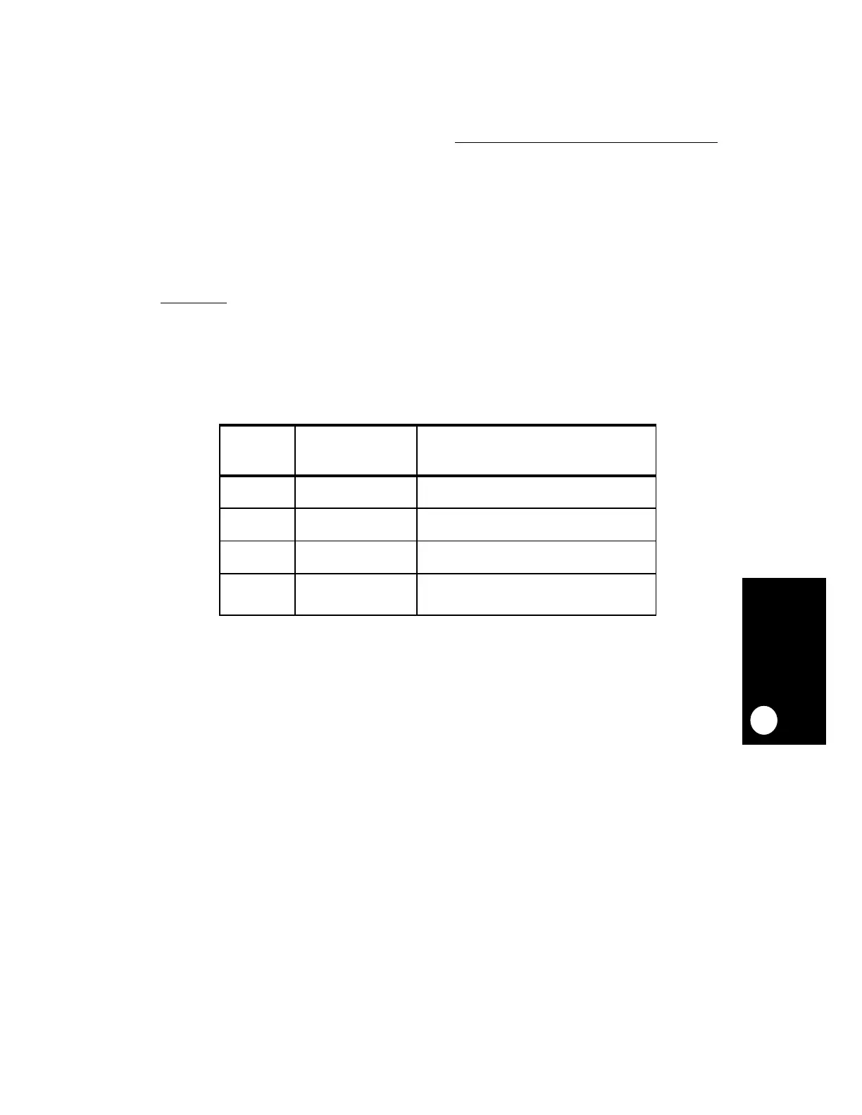
Table 5-1. Power-On Reset Clock Configuration
MODCK [1:2] DEFAULT
MF + 1 AT
POWER-ON RESET
SPLL OPTIONS
00 513 Normal operation, SPLL enabled.
Main timing reference is OSCM
freq
= 32 kHz.
01 5 Normal operation, SPLL enabled.
Main timing reference is OSCM
freq
= 4 MHz.
11 5 Normal operation, SPLL enabled.
Main timing reference is EXTCLK
freq
= 4 MHz.
10 1 Normal operation, SPLL enabled.
One-to-one Mode Maximum
OSCM
freq
= EXTCLK
freq
 Loading...