External Bus Interface
MOTOROLA MPC823e REFERENCE MANUAL 13-37
EXTERNAL BUS
13
INTERFACE
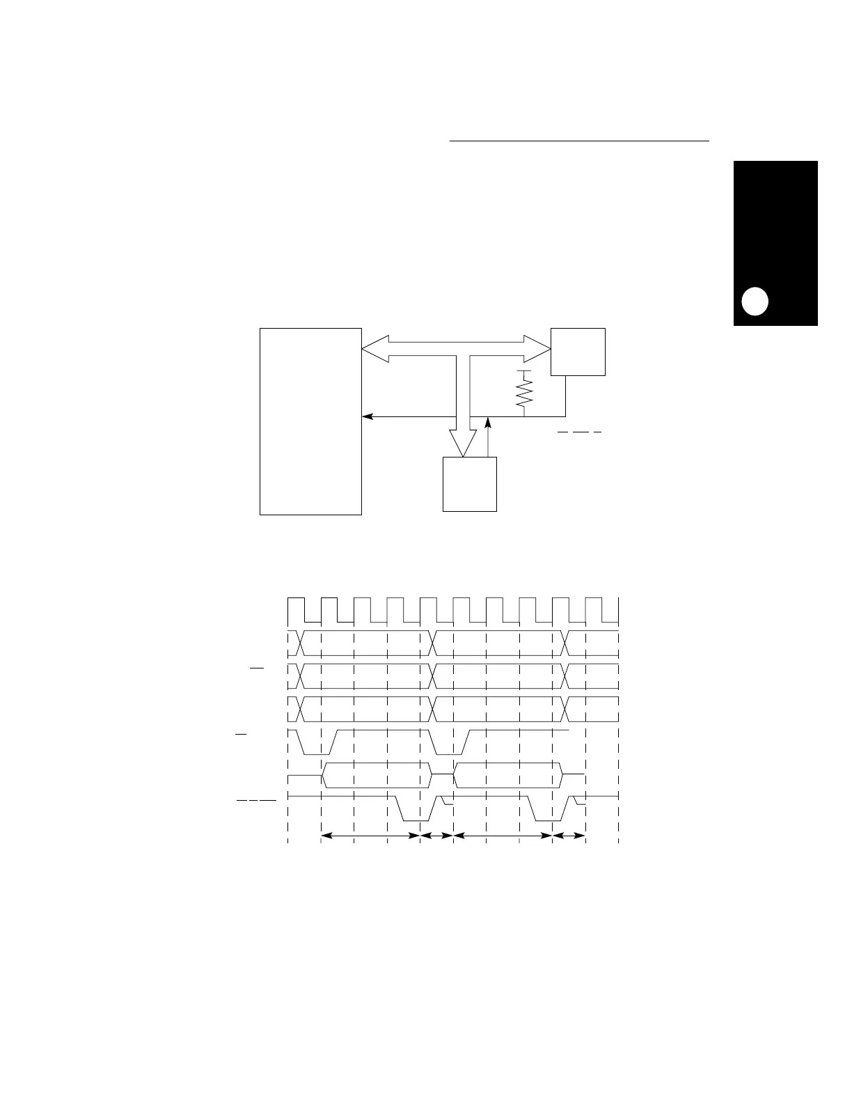
13.4.9.4 PROTOCOL FOR TERMINATION SIGNALS. The transfer protocol was defined
to avoid electrical contention on signals that can be driven by various sources. To do that, a
slave must not drive signals associated with the data transfer until the address phase is
completed and it recognizes the address as its own. The slave must disconnect from signals
immediately after it has acknowledged the cycle and no later than the termination of the next
address phase cycle. This indicates that the termination signals must be connected to power
through a pull-up resistor to avoid a situation in which a master samples an undefined value
in any of these signals when no real slave is addressed. See Figure 13-24 and
Figure 13-25 for more information.
Figure 13-24. Termination Signals Protocol Basic Connection
Figure 13-25. Termination Signals Protocol Timing Diagram
EXTERNAL BUS
MPC823e
SLAVE 2
SLAVE 1
ACKNOWLEDGE/TERMINATION
SIGNALS (TA
, TEA, BI)
CLKOUT
A[6:31]
TS
TA,BI,TEA
RD/WR
TSIZ[0:1]
SLAVE 1 SLAVE 2
SLAVE 1
ALLOWED TO
DRIVE
SLAVE 1
NEGATES
ACKNOWLEDGE
SIGNALS
AND
TURNS OFF
ACKNOWLEDGE
SIGNALS
SLAVE 2
ALLOWED TO
DRIVE
SLAVE 2
NEGATES
ACKNOWLEDGE
SIGNALS
AND
TURNS OFF
ACKNOWLEDGE
SIGNALS
DATA
 Loading...