External Bus Interface
MOTOROLA
MPC823e REFERENCE MANUAL
13-33
EXTERNAL BUS
13
INTERFACE
13.4.7.3.3 Transfer Size Signal.
The TSIZx signals indicate the size of the requested data
transfer and they can be used with the BURST
and A[30:31] signals to determine the byte
lanes of the data bus that are involved in the transfer. For nonburst transfers, the TSIZx
signals specify the number of bytes starting from the byte location addressed by the A[30:31]
signals. In burst transfers, the value of the TSIZx signal is always 00.
13.4.7.3.4 Address Space Attributes.
The address space attributes consist of the
address type (AT[0:3]), program trace (PTR
), and reservation (RSV) signals, which are all
outputs that indicate one of 16 “address types” to which the address applies. These types
are designated as either a normal/alternate master cycle, problem/privilege (user or
supervisor), and instruction or data types. The address space signals are valid at the rising
edge of the clock in which the STS
signal is asserted.
Address space signals reflect the current status of the master originating the access, not
necessarily the status in which the original access to this location has occurred. An example
of this situation is when a copyback of a dirty line in the data cache occurs after the privilege
state of the processor has been changed since the last access to the same line. Functional
usage of the ATx, PTR
, and RSV signals is for the reservation protocol described in
Section 13.4.10 Storage Reservation Protocol
. Table 13-5 provides the space definition
encoded by the STS
, TS, ATx, PTR, and RSV signals.
Show cycles are accesses to the core’s internal bus devices. These accesses are driven
externally for emulation, visibility, and debugging purposes. A show cycle can have one
address phase and one data phase (or just an address phase for the instruction show
cycles). The cycle can be a write or read access and the data for both the read and write
accesses must be driven by the bus master. This is different than the normal bus read and
write accesses. The address of the show cycle must be valid on the bus for one clock and
the data of the show cycle must be valid on the bus for one clock. The data phase must not
require a transfer acknowledge to terminate the bus-show cycle. In a burst show cycle only
the first data beat will be shown externally.
13.4.7.3.5 Special Transfer Start Signal.
The STS
signal is driven by the MPC823e when
it owns the external bus. It indicates the start of a transaction on the external bus or an
internal transaction in show cycle mode.
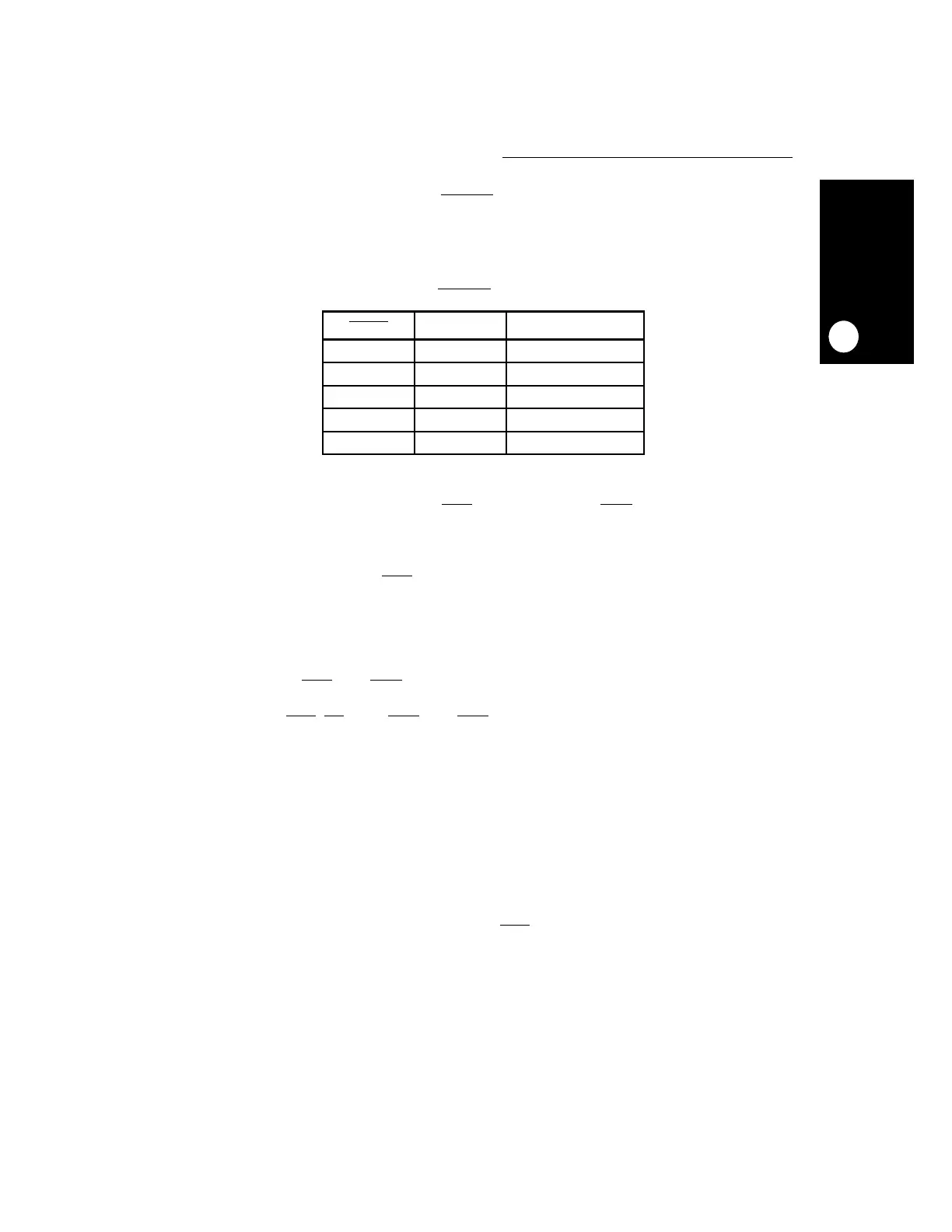
Table 13-4. BURST
/TSIZE Encoding
BURST
TSIZx TRANSFER SIZE
1 01 Byte
1 10 Half-Word
111 x
1 00 Word
0 00 Burst (16 bytes)
 Loading...