External Bus Interface
MOTOROLA MPC823e REFERENCE MANUAL 13-25
EXTERNAL BUS
13
INTERFACE
13.4.5 Transfer Alignment and Packaging
The MPC823e external bus only supports natural address alignment that forces the
following restrictions:
• Byte access can have any address alignment
• Half-word access must have address bit 31 equal to 0
• Word access must have address bits 30-31 equal to 0
• For burst access must have address bits 30-31 equal to 0
The MPC823e can perform operand transfers through its 32-bit data port. If the transfer is
controlled by the internal memory controller, the MPC823e can support 8- and 16-bit data
port sizes. The bus requires that the portion of the data bus used for a transfer to or from a
particular port size to be fixed. A 32-bit port must reside on data bus bits 0-31, a 16-bit port
must reside on bits 0-15, and an 8-bit port must reside on bits 0-7. The MPC823e always
tries to transfer the maximum amount of data on all bus cycles and for a word operation it
always assumes that the port is 32 bits wide at the beginning of the bus cycle. In Figure 13-
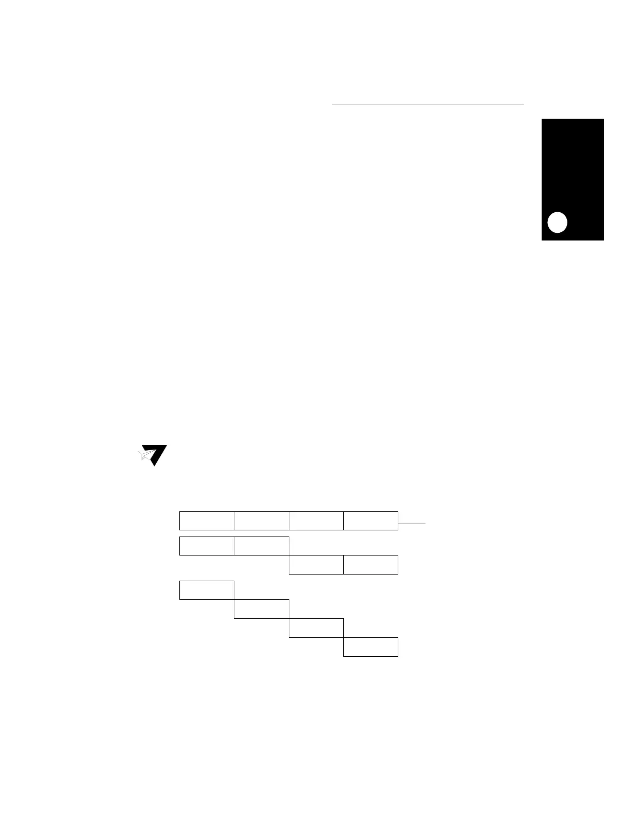
18 and Figure 13-19 and Table 13-2 and Table 13-3, the following operand conventions
have been adopted:
• OP0 is the most-significant byte of a word operand and OP3 is the least-significant byte.
• The two bytes of a half-word operand are OP0 (most-significant) and OP1 or OP2
(least-significant) and OP3, depending on the address of the access.
• The single byte of a byte-length operand is OP0, OP1, OP2, or OP3, depending on the
address of the access.
Note: Although this is a 32-bit machine, only 26 of the bits are visible outside the chip.
Figure 13-18. Internal Operand Representation
OP0 OP1 OP2
0 31
WORD
HALF-WORD
BYTE
OP0
OP1
OP2
OP3
OP0 OP1
OP2 OP3
OP3
 Loading...

