Programming and Operating Manual (Milling)
102 6FC5398-4DP10-0BA6, 09/2017
Note
A complete cycle of tapping with compensating chuck is provid
ed by the standard cycle CYCLE840.
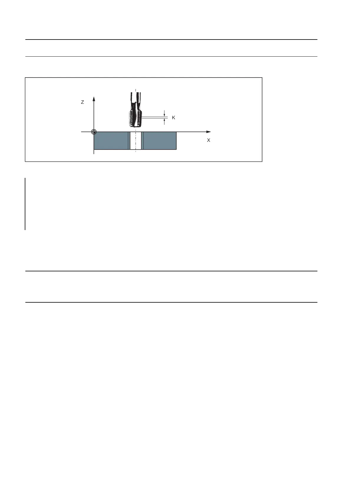
See the following illustration for tapping using G33:
; pitch as per table: 0.8 mm/rev., hol e already
premachined
N10 G54 G0 G90 X10 Y10 Z5 S600 M3
; Approach starting point, clockwise s pindle rota-
tion
; Tapping, end point -25 mm
; Retraction, counter-clockwise spindle rotation
With G33 threads, the velocity of the axis for the thread lengths is determined on the basis of the spindle speed and the
thread pitch. The
feedrate F is not relevant
. It is, however, stored. However, the maximum axis velocity (rapid traverse)
defined in the machine data cannot be exceeded. This will result in an alarm.
The spindle speed override switch must remain unchanged for thread machining.
• The feedrate override switch has no meaning in this block.
Tapping with compensating chuck: G63
Fu n ctionality
G63 can be used for tapping with compensating chuck. The programmed feedrate F must match with the spindle speed S
(programmed under the address "S" or specified speed) and with the thread pitch of the drill:
F [mm/min] = S [rpm] x thread pitch [mm/rev.]
The compensating chuck compensates the resulting path differences to a certain limited degree.
The drill is retracted using G63, too, but with the spindle rotating in the opposite direction M3 <-> M4.
G63 is non-modal. In the block after G63, the previous G command of the "Interpolation type" group (G0, G1,G2, ...) is active
again.
Right-hand or left-hand thread
Right-hand or left-hand thread is set with the rotation direction of the spindle (M3 right (CW), M4 left (CCW) - see Section
"Spindle movements (Page 109)").