Programming and Operating Manual (Milling)
226 6FC5398-4DP10-0BA6, 09/2017
Use the parameter _DP1 to define the infeed depth when inserting to the helical path.
A tool compensation must be programmed before the cycle is called. Otherwise, the cycle is aborted and alarm 61000 "No
tool compensation active" is output.
Internally in the cycle, a new current workpiece coordinate system is used which influences the actual value display. The
zero point of this coordinate system is to be found in the pocket center point. At the end of the cycle, the original coordinate
system is active again.
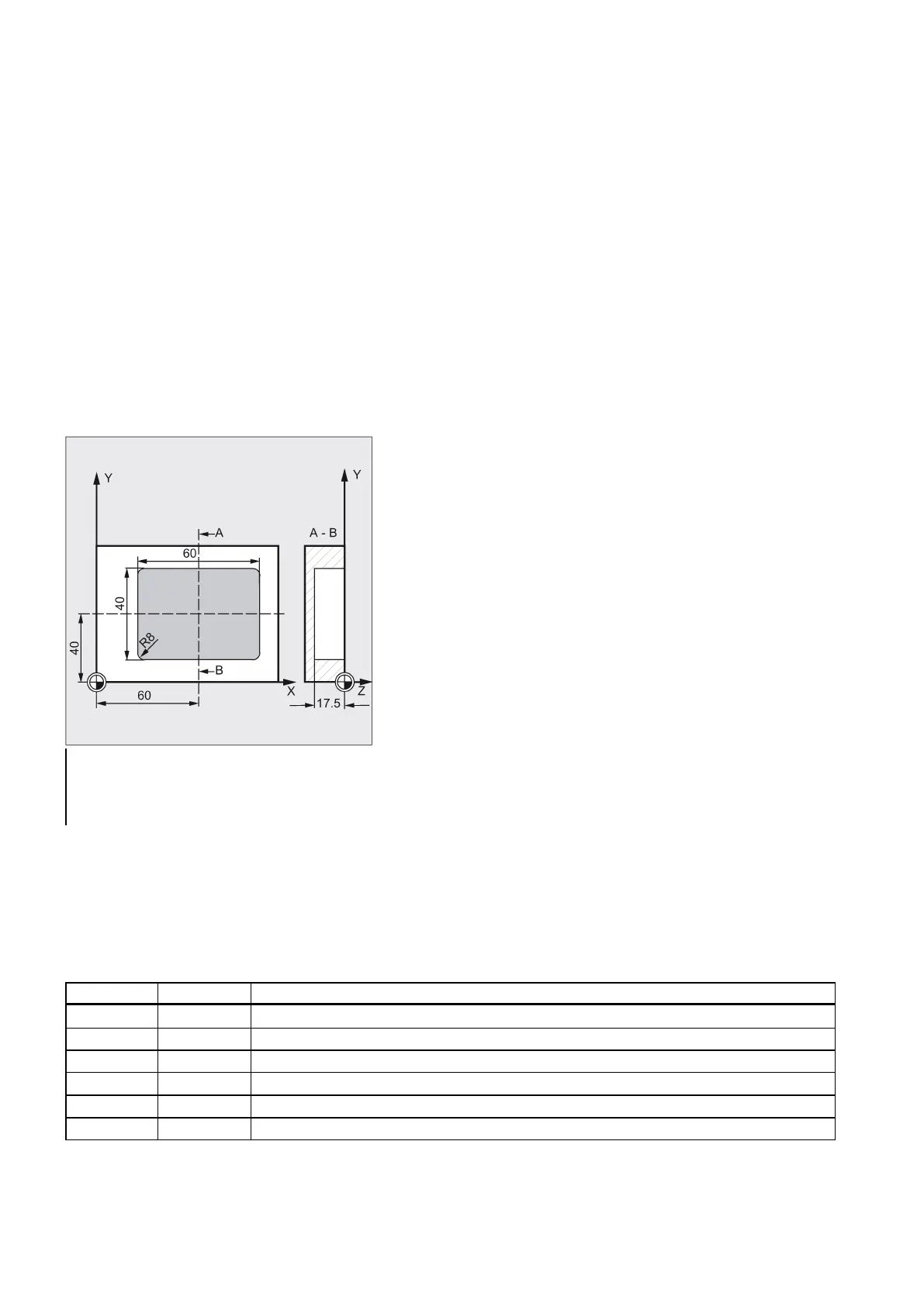
Programming example: Pocket
Use this program to machine a pocket in the XY plane which is 60 mm in length, 40 mm in width, and which has a corner
radius of 8 mm and is 17.5 mm in depth. The pocket has an angle of 0 degrees to the X axis. The final machining allowance
of the pocket edges is 0.75 mm, 0.2 mm at the base, the safety clearance in the Z axis, which is added to the reference
plane, is 0.5 mm. The center point of the pocket lies at X60 and Y40, the maximum depth infeed is 4 mm.
The machining direction results from the direction of rotation of the spindle in the case of down-cut milling. A milling cutter
with 5 mm radius is used.
Merely a rough machining operation is to be carried out.
See the following programming example for rectangular pocket:
; Specification of technology values
; Approach starting position
N30 POCKET3(5, 0, 0.5, -17.5, 60, 40, 8, 60, 40, 0, 4,
0.75, 0.2, 1000, 750, 0, 11, 5, , , , , )
Milling a circular pocket - POCKET4
Programming
POCKET4 (_RTP, _RFP, _SDIS, _DP, _PRAD, _PA, _PO, _MID, _FAL, _FALD, _FFP1, _FFD, _CDIR, _VARI, _MIDA, _AP1,
_AD, _RAD1, _DP1)
Retraction plane (absolute)
Reference plane (absolute)
Safety clearance (to be added to the reference plane; enter without sign)
_DP REAL Pocket depth (absolute)
_PRAD REAL Pocket radius
Pocket center point, abscissa

 Loading...


