Programming and Operating Manual (Milling)
186 6FC5398-4DP10-0BA6, 09/2017
The drilling tool in the program traverses all programmed positions in the order in which you program them. Machining of the
positions always starts at the reference point. If the position pattern consists of only one position, the tool is retracted to the
retraction plane after machining.
Explanation of the parameters
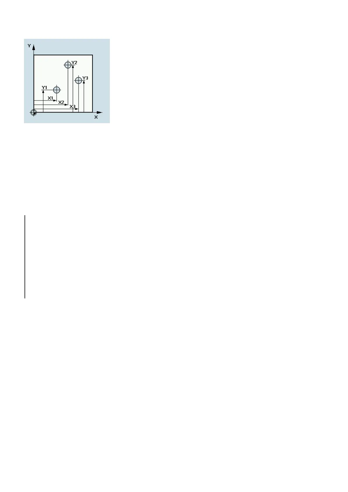
X0, Y0...X4, Y4
All positions will be programmed absolutely.
Drilling in G17 at the Positions
; Absolu te dimension data X/Y plane
; Spindle speed clockwise rotation of the spindle
; Approach starting position
MCALL CYCLE82 (2, 0, 2, -5, 5, 0)
; Modal cal l of the drill ing
N40 CYCLE802 (111111111, 111111111, 20, 20, 40,
25, 30, 40)
Requirements
Call and return conditions
Milling cycles are programmed independently of the particular axis name.
Before you call the milling cycles, a tool compensation must be activated.
The appropriate values for feedrate, spindle speed and direction of rotation of spindle must be programmed in the part
program if the appropriate parameters are not provided in the milling cycle.
The center point coordinates for the milling pattern or the pocket to be machined are programmed in a rectangular
coordinate system.
The G functions active prior to the cycle call and the current programmable frame remain active beyond the cycle.

 Loading...


