Programming and Operating Manual (Milling)
6FC5398-4DP10-0BA6, 09/2017
311
The meaning of the symbol colors in the contour chain on the left of the main screen is as follows:
Selected Symbol color black on a red background → Element is defined geometrically
Symbol color black on a light yellow background → Element is not defined geometrically
Not selected Symbol color black on a gray background → Element is defined geometrically
Symbol color white on a gray background → Element is not defined geometrically
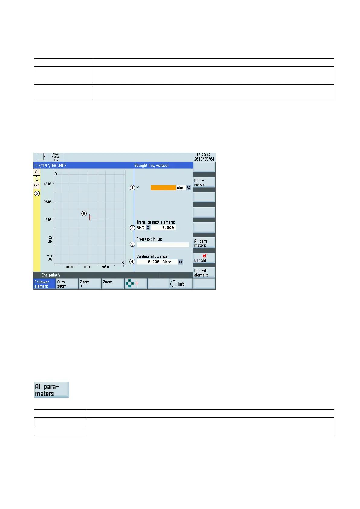
Parameters for contour elements
Parameters for programming straight lines
Absolute (abs)/incremental (inc) end position in X or Y direction
Transition element to the next contour is a chamfer (CHR) or a radius (RND). CHR=0 or RND=0 means no transition
element.
③
Input field for supplementary comments, such as F1000 feedrate values, H or M functions. If comments are entered as
text, they must always be started with a semicolon ";".
④
-based parallel contour allowance. It is displayed as an allowance in the graphics window.
⑤
The contour chain which displays the start point and programmed contour elements. The current position in the chain
is color
-highlighted.
The graphics window which displays the progress of the contour as you configure the parameters for the contour el
e-
The following additional parameters are displayed after you press this softkey:
L Length of the straight line
Pitch angle with reference to Y axis

 Loading...


