Programming and Operating Manual (Milling)
182 6FC5398-4DP10-0BA6, 09/2017
R15=20
R16=0
R17=10
R18=10
R19=5
R20=5
R21=0
R22=10
; Reference point for the row of holes in the first axis of
the plane
; Reference point for the row of holes in the seco nd axis of
the plane
; Starting angle
; Distan ce from first hole to refer enc e point
; Distance between the holes
; Number of holes per row
; Number of rows
; Row counter
; Distance between the rows
N10 G90 F300 S500 M3 T10 D1
; Specification of the technological v alues
N20 G17 G0 X= R14 Y=R15 Z1 05
; Approach starting position
N30 MCAL L CYCLE82( R11, R10, R12, R13,
0, 1)
; Modal cal l of drilling cycle
; Call of row of holes cycle
N41 HOLES1(R14, R15, R16, R1 7, R18,
R19)
; Calculate y value for the next line
N70 IF R21<R20 GOTOB LABEL1
; Return to LABEL1 if the condition is fulfilled
; Approach starting position
Circle of holes - H OLES2
Programming
HOLES2 (CPA, CPO, RAD, STA1, INDA, NUM)
Center point of circle of holes (absolute), first axis of the plane
CPO REAL Center point of circle of holes (absolute), second axis of the plane
Radius of circle of holes (enter without sign)
STA1 REAL Starting angle
Range of values: -180<STA1≤180 degrees
NUM INT Number of holes
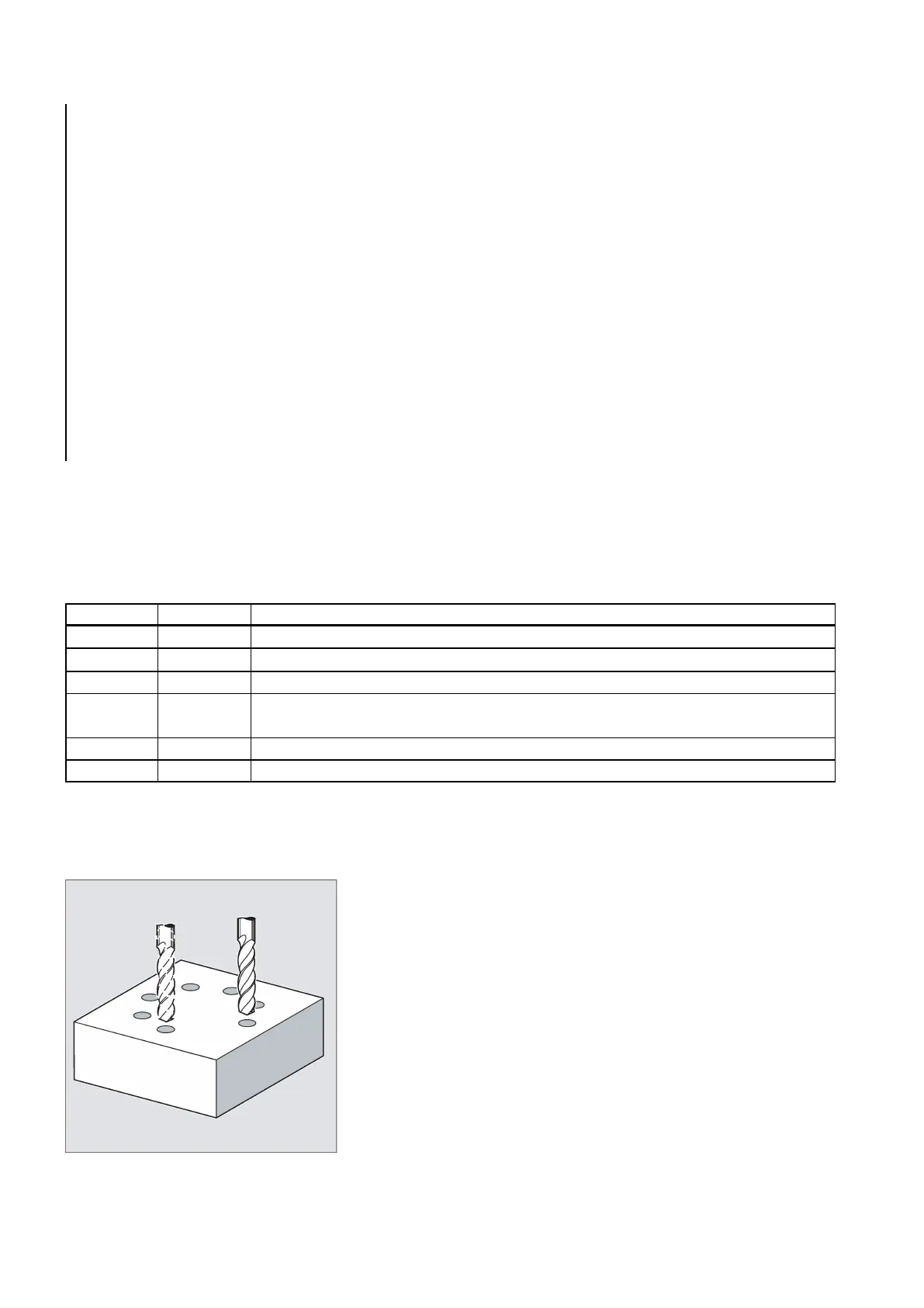
Use this cycle to machine a circle of holes. The machining plane must be defined before the cycle is called.
The type of hole is determined through the drilling cycle that has already been called modally.

 Loading...


