Programming and Operating Manual (Milling)
6FC5398-4DP10-0BA6, 09/2017
27
Measuring the tool manually
• You must first create a tool (Page 21) and activate it (Page 23) before measuring the tool.
• This section takes the milling tool measurement for example. If you have created other types of tools, proceed through
the following steps to finish the measurement of all the tools. This will make the tool change process easier.
Select the machining operating area.
Open the tool measurement window.
Open the manual tool measurement window.
Press the axis traversing keys to move the infeed axes to the desired positions above the
workpiece.
Switch to handwheel control mode.
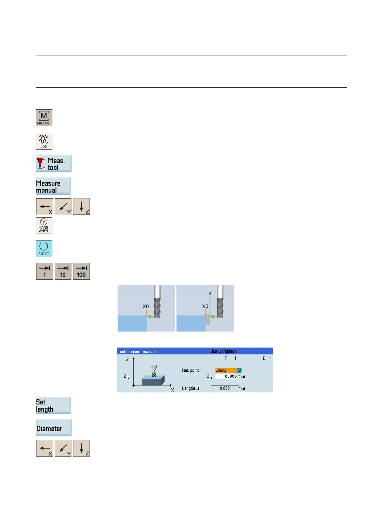
Press this key to set the workpiece or a fixed point as the reference point.
Note
:
You can define a fixed point as desired, for example, the workbench.
Select a suitable override feedrate, and then use the handwheel to move the tool to scratch
the required workpiece edge (see the left illustration shown below) or the edge of the setting
block, if it is used (see the right illustration shown below).
Enter the distance between the tool tip and the reference point in the "Z0" field, for example,
"0". (This value is the thickness of a setting block if it is used.)
Save the tool length value in the Z axis. The tool diameter, radius, and cutting edge position
are all taken
in to account.
Press this vertical softkey to open the window for measuring the tool diameter.
Press the axis traversing keys to move the tool to approach the workpiece in the X direction.

 Loading...


