Programming and Operating Manual (Milling)
134 6FC5398-4DP10-0BA6, 09/2017
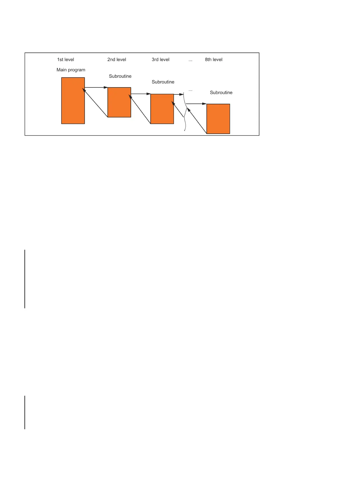
See the following illustration for execution with 8 program levels:
Modal G functions can be changed in the subroutine, e.g. G90 -> G91. When returning to the calling program, ensure that all
modal functions are set the way you need them to be.
Please make sure that the values of your arithmetic parameters used in upper program levels are not inadvertently changed
in lower program levels.
When working with SIEMENS cycles, up to 4 program levels are needed.
Calling machining cycles
Fu n ctionality
Cycles are technology subroutines realizing a certain machining process generally, for example, drilling or milling.
Adaptation to the particular problem is performed directly via supply parameters/values when calling the respective cycle.
N10 DEF REA L RTP, RFP, SDIS, DP, DTB
N50 CYCLE83(110, 90, 0, -80, 0, -10, 0, 0, 0, 0, 1, 0)
; Call of cycle 83, transfer values di rectly,
separate block
N70 RTP=100 RFP= 95.5 SDIS=1, DP= -5, DTB=3
; Set transfer parameters for cycle 82
N80 CYCLE82(RTP, RFP, SDIS, DP, , DTB)
; Call of cycle 82, separate block
Modal subroutine call
Fu n ctionality
The subroutine in the block containing MCALL is called automatically after each successive block containing a
.
The call acts until the next MCALL is called.
The modal call of the subroutine which contains MCALL or quitting of the call requires a separate block.
MCALL is advantageous, for example, when producing drill patterns.
Application example: Drilling a row of holes
N10 MCALL CYCLE82(100, 0, 1, -10, 2)
N20 HOLES1(1, 2, 45, 2, 2, 1)
; Cycle for row of holes; after each a pproach
of the hole position, CYCLE82(...) wil l be
called with the transfer parameters
; Modal cal l of CYCLE82(...) completed

 Loading...


