Programming and Operating Manual (Milling)
6FC5398-4DP10-0BA6, 09/2017
187
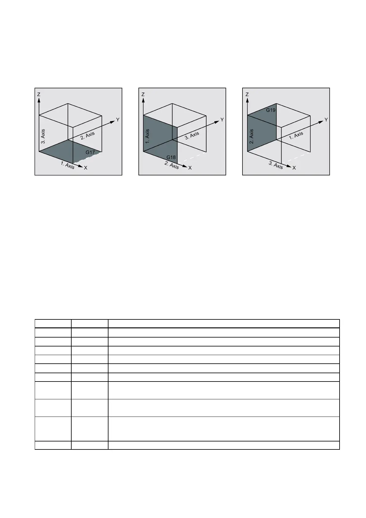
Milling cycles generally assume that the current workpiece coordinate system has been defined by selecting a plane (G17,
G18 or G19) and activating a programmable frame (if necessary). The infeed axis is always the third axis of this coordinate
system.
See the following illustration for plane and axis assignment:
Messages with regard to the machining state
During the execution of the milling cycles, various messages that refer to the machining status are displayed on the screen.
The following messages are possible:
● "Elongated hole <No.>(first figure) being machined"
● "Slot <No.>(other figure) being machined"
● "Circumferential slot <No.>(last figure) being machined"
In each case, <No.> stands for the number of the figure that is currently being machined.
These messages do not interrupt the program execution and continue to be displayed until the next message is displayed or
the cycle is completed.
Face milling - C Y CLE71
Programming
CYCLE71 (_RTP, _RFP, _SDIS, _DP, _PA, _PO, _LENG, _WID, _STA, _MID, _MIDA, _FDP, _FALD, _FFP1, _VARI, _FDP1)
Retraction plane (absolute)
_RFP REAL Reference plane (absolute)
Safety clearance (to be added to the reference plane; enter without sign)
_PA REAL Starting point (absolute), first axis of the plane
Starting point (absolute), second axis of the plane
_LENG REAL Rectangle length along the first axis, incremental.
The corner from which the dimension starts results from the sign.
_WID REAL Rectangle length along the second axis, incremental.
The corner from which the dimension starts results from the sign.
_STA REAL Angle between the longitudinal axis of the rectangle and the first axis of the plane (abscissa,
enter without sign).
Range of values: 0° ≤ STA < 180°
_MID REAL Maximum infeed depth (enter without sign)
 Loading...


