Programming and Operating Manual (Milling)
28 6FC5398-4DP10-0BA6, 09/2017
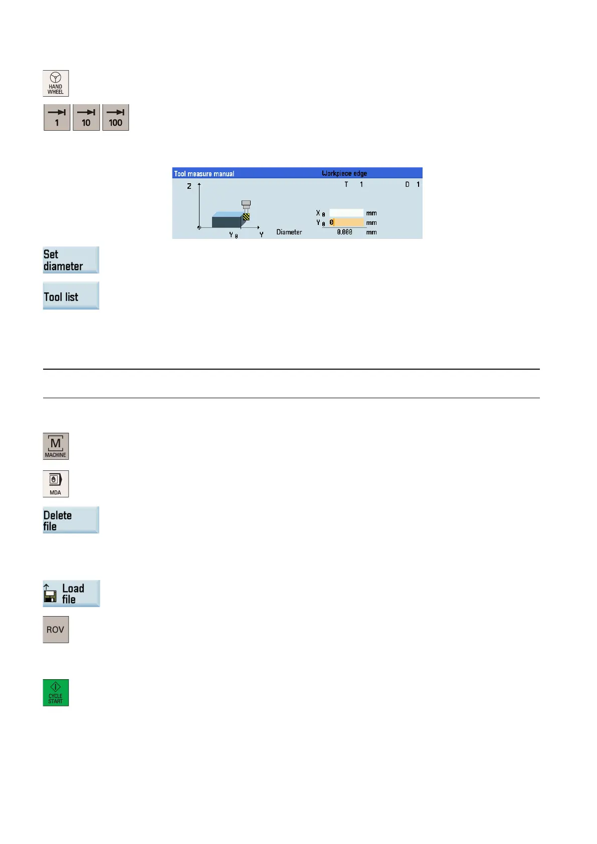
Switch to handwheel control mode.
Select a suitable override feedrate, and then use the handwheel to move the tool to scratch
the required workpiece edge (or the edge of the setting block, if it is used).
Enter the distance to the workpiece edge in the X and Y directions in the "X0" and "Y0"
fields respectively, for example, enter "0" at "X0" and "0" at "Y0". (This is the value of the
width of a setting block if it is used. Select one of X0/Y0 as required.)
Save the tool diameter value.
Press this softkey and you can see that the compensation data values have been automati-
cally added to the tool data.
Verifying the tool offset result
To guarantee the safety and correctness of machining, you must verify the tool setup result.
Note
Before verifying the tool setup result, you must have finished all tool setup work as mentioned before.
Select the machining operating area.
Press this softkey on the PPU.
Enter the following test program (or you can create your own program):
T1 D1
Alternatively, you can press this softkey to load an existing part program from a system
directory.
Press this key to activate the "ROV" function (indicator on: this function is active).
Note:
After the "ROV" function is active, the feedrate override switch can also control the speed of
G00.
Rotate the feedrate override switch to 0%.
Press this key on the MCP.
Increase the feedrate override gradually to avoid accidents caused by fast axis movement.
Observe whether the axis moves to the specified position.
For more information on the further softkey functions in "MDA" mode, see Section ""MDA" mode (Page 295)".

 Loading...


