Programming and Operating Manual (Milling)
288 6FC5398-4DP10-0BA6, 09/2017
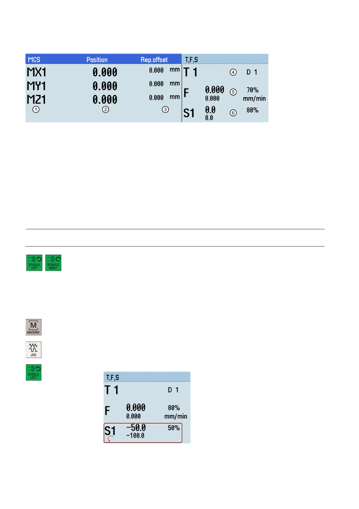
Parameters in the "JOG" window
Displays the axes that exist in the machine coordinate system (MCS), workpiece coordinate system (WCS), or relative
coordinate system(REL).If you traverse an axis in the positive (+) or negative (
-) direction, a plus or minus sign ap-
pears in the relevant field. If the axis is already in the required position, no sign is displayed.
Displays the current position of the axes in the selected coordinate system.
Displays the distance traversed by each axis in "JOG" mode from the interruption point in the
condition of program
interruption. For more information about program interruption, see Section "
Executing a part program (Page 46)".
the currently active tool number T with the current tool offset number D.
Displays the actual axis feedrate and the setpoint (mm/min or mm/rev).
Displays the actual value and the setpoint of the spindle speed (r.p.m.).
Running the spindle manually
Note
Before running the spindle manually, make sure you have activated the tool.
/
You can run the spindle manually using these keys on the MCP in "JOG" mode. The spindle
speed is selected via MD14512[19].4 as follows:
• MD14512[19].4 = 0 (default): the spindle runs with the speed set in MD32020.
• MD14512[19].4 = 1: the spindle runs with the speed set last time. In this case, if the spindle
runs for the first time after the control system powers on, then you must specify a spindle
speed in "MDA" mode or the "T, S, M" window.
Select the machining operating area.
Press this key on the MCP to rotate the spindle counter-clockwise.

 Loading...


