Programming and Operating Manual (Milling)
6FC5398-4DP10-0BA6, 09/2017
39
Tool and traverse (T, D, M6, F, G94/G95, S, M3/M4, G01)
A new tool can be selected with the "T" command, and the "D" command
is used to activate the tool length offset.
M6 can be used for automatic tool change on the machine.
The feedrate is defined with "F". G94 F defines feedrate in terms of time
(mm/min) and G95 F defines feedrate in terms of spindle revolutions
(mm/rev).
The spindle speed is defined with "S". The spindle direction is defined
with M3(clockwise) and M4 (counter-clockwise).
When G01 is active in the program, the axis traverses at the pro-
grammed feedrate (as defined by G94 F or G95 F) in a straight line.
N10 G17 G90 G54 G71
N20
N30
N40 G00 X50 Y50 Z5
N50
Z-5
N60 Z5
N70 G00 Z500 D0
For more information, see sections as follows:
● Tool T (Page 116)
● Tool compensation number D (Page 116)
● Feedrate F (Page 92)
● Spindle speed S, directions of rotation (Page 109)
● Linear interpolation with feedrate: G1 (Page 92)
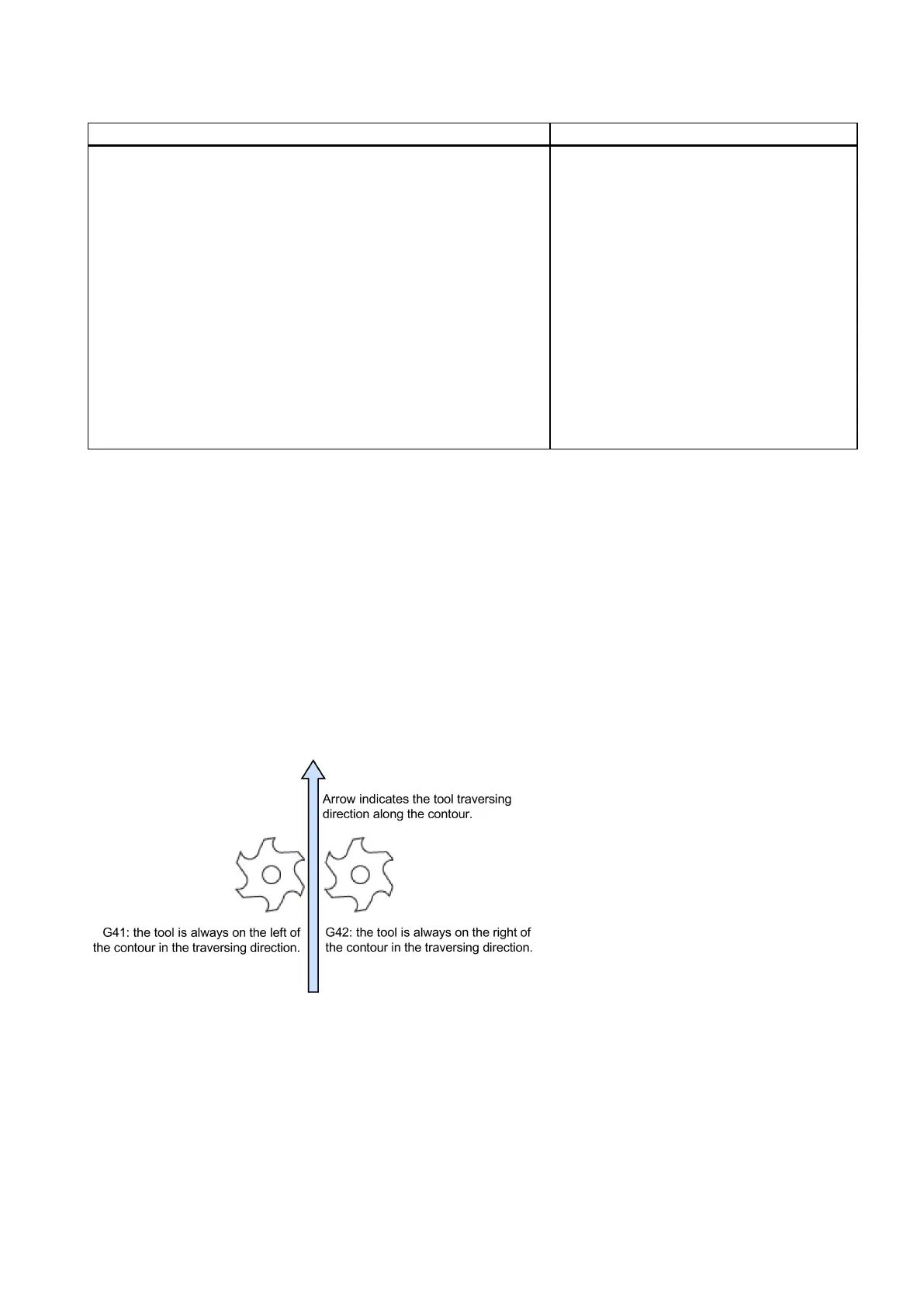
Tool radius compensation (G40, G41/G42)
The tool radius compensation can be activated (G41/G42) or deactivated (G40) in contour programming.
● G41: tool radius compensation to the left of the contour
● G42: tool radius compensation to the right of the contour
● G40: tool radius compensation off
When traversing circle contours with cutter radius compensation, it must be decided whether the feedrate should act at the
circle contour of the workpiece (CFC) or the path defined by the cutter center point (CFTCP).
When using the feedrate at the circle contour defined by the CFC command, the feedrate is constant at the contour, which
however may cause increase in the feedrate of the tool. This increase could damage the tool if excessive material is
encountered at the contour. Therefore, CFC is commonly used for finish cutting of contours.
The CFTCP command ensures a constant feedrate of the tool, but different feedrates at the contour. This may cause
deviations in surface finish.

 Loading...


