Programming and Operating Manual (Milling)
6FC5398-4DP10-0BA6, 09/2017
17
Workpiece coordinate system (WCS)
To describe the geometry of a workpiece in the workpiece program, a right-handed, right-angled coordinate system is also
used.
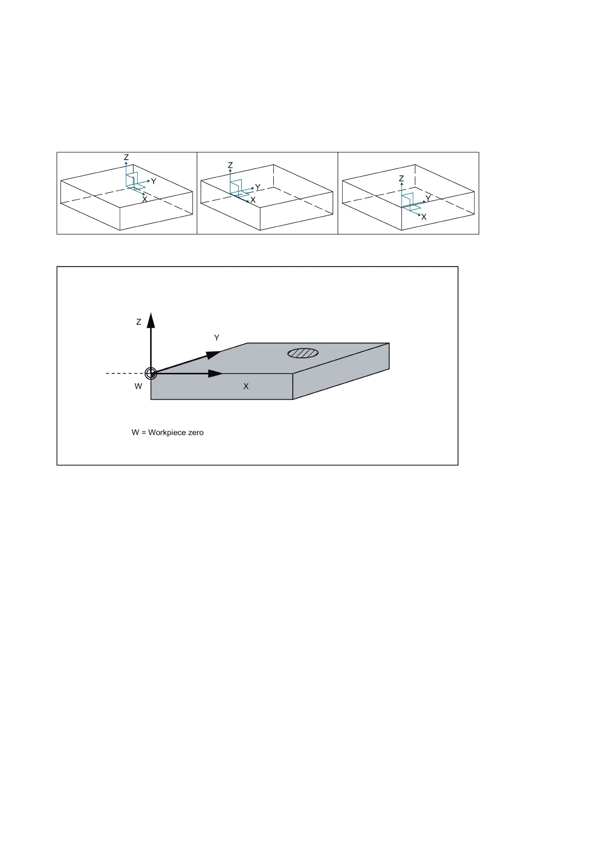
Generally, X0/Y0 of the WCS is set at the center, edge or corner of the workpiece while Z0 is set on the top surface of the
workpiece.
See the following illustrations for X0/Y0 at the center, edge and corner of the workpiece respectively.
The figure below shows an example of the workpiece coordinate system.
Relative coordinate system (REL)
In addition to the machine and workpiece coordinate systems, this control system provides a relative coordinate system.
This coordinate system can clear the current coordinate values at any position and has no influence on workpiece machining
or the position of WCS. All axis movements are displayed relative to this position.

 Loading...


