Two-channel brake control
Note
Connecting the brake
The brake cannot be directly connected to the Motor Module in chassis format: A Safe Brake
Adapter is also required.
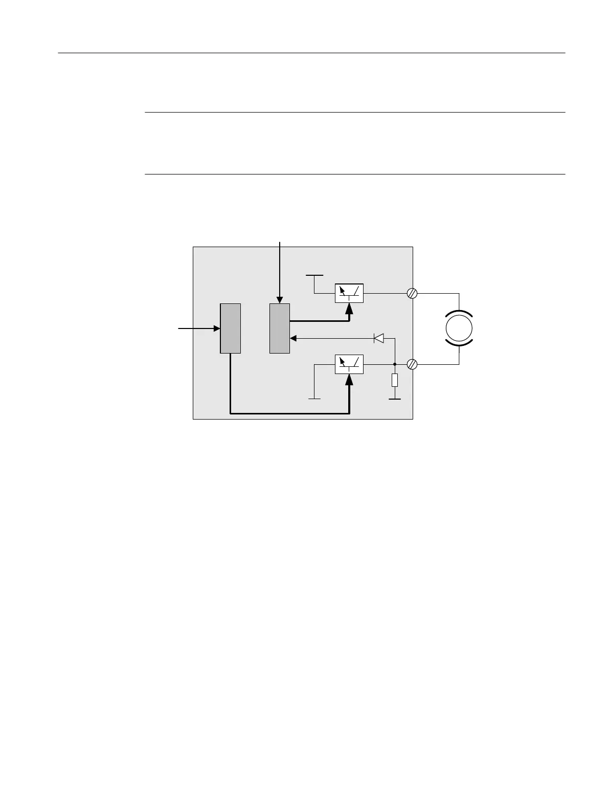
The brake is controlled from the Control Unit. Two signal paths are available for applying the
brake.
&RQWURO
WHUPLQDO
%UDNHGLDJQRVWLFV
&ORVHGFLUFXLWEUDNH
0RWRU
7%
&RQWURO8QLW0RWRU
0RGXOH6DIH%UDNH
5HOD\
&RQWUROWHUPLQDO
%5
%5
3
%5
%5
00
7%
Figure 4-2 Two-channel brake control, blocksize (example)
For the "Safe Brake Control" function, the Motor/Power Module assumes a monitoring function
to ensure that when the Control Unit fails or malfunctions, the brake current is interrupted
therefore closing the brake.
The brake diagnosis can only reliably detect a malfunction in either of the switches (TB+, TB-)
when the status changes, i.e. when the brake is released or applied.
If the Motor Module or Control Unit detects a fault, the brake current is switched off. The brake
then closes and a safe state is reached.
4.5.1.1 SBC for Motor Modules in the chassis format
To be able to set higher power in the brakes of devices of this format, an additional Safe Brake
Adapter (SBA) module is needed. For more information about connecting and wiring the Safe
Brake Adapter, refer to the "SINAMICS G130/G150/S120 Chassis/S120 Cabinet Modules/
S150 Safety Integrated" Function Manual.
Using parameter p9621, you can define via which digital input the relay (NO contacts) feedback
signal of the Safe Brake Adapter is routed to the Control Unit.
To evaluate the feedback signal contacts, you must maintain the wait times caused by the SBA.
Parameter p9622 is pre-assigned with the SBA-relay wait times:
● p9622[0] ≙ wait time, switching on
● p9622[1] ≙ wait time, switching off
Safety functions integrated in the drive
4.5 SBC (Basic/Extended)
Safety Integrated (with SINAMICS S120)
Commissioning Manual, 02/2020, A5E46305916B AB 111

 Loading...