4.5.1.2 Function diagrams and parameters
Function diagrams (see SINAMICS S120/S150 List Manual)
● 2814 SI Basic Functions - SBC (Safe Brake Control), SBA (Safe Brake Adapt‐
er)
Overview of important parameters (see SINAMICS S120/S150 List Manual)
● p0799 CU inputs/outputs, sampling time
● p1215 Motor holding brake configuration
● p7015 Par_circuit holding brake power unit data set
● p9602 SI enable safe brake control (Control Unit)
● p9621 BI: SI Safe Brake Adapter signal source (Control Unit)
● p9622[0...1] SI SBA relay wait times (Control Unit)
● r9771.14 SI common functions (Control Unit): SBC supported for parallel connec‐
tion
● r9780 SI monitoring cycle (Control Unit)
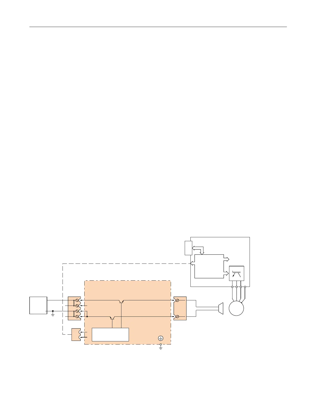
4.5.1.3 Hardware required, SBR and SBA
● Safe Brake Relay
The command for releasing or applying the brake is transferred to the Motor Module / Power
Module via DRIVE-CLiQ. The Motor Module / Safe Brake Relay then carries out the action
and appropriately activates the outputs for the brake.
Cable harness
PM-IF interface
M
3 ~
Power Module
BR+
BR-
M
M
CTRL
Safe Brake Relay
+
M
PE
W2
V2
U2
ext.
24 V
+
+
Figure 4-3 Interconnecting the Safe Brake Relay using Blocksize as an example
Safety functions integrated in the drive
4.5 SBC (Basic/Extended)
Safety Integrated (with SINAMICS S120)
Commissioning Manual, 02/2020, A5E46305916B AB 113

 Loading...