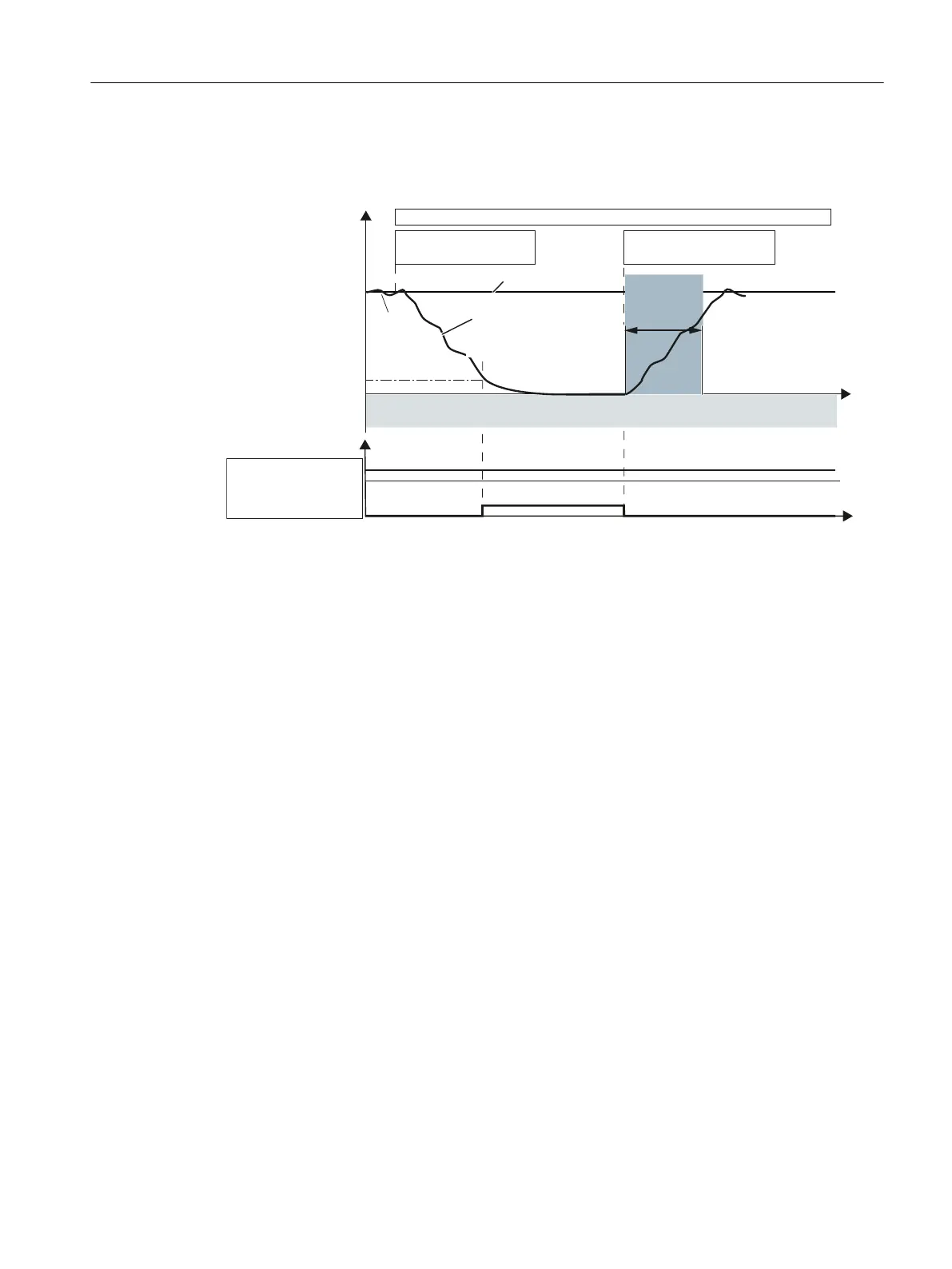
Switching the motor on and off (without encoder)
The time response and diagnostic options are as follows in this SDI version:
6ZLWFKRQPRWRU
21FRPPDQG
=HURVSHHG
GHWHFWLRQ
5DPSIXQFWLRQ
JHQHUDWRUUDPSGRZQ
WLPH
6HWSRLQW
$FWXDO
YDOXH
6ZLWFKRIIWKHPRWRU
2))FRPPDQG
/RDGVSHHG
'LDJQRVWLFV
2SHUDWRUDFWLRQV
6',DFWLYH
6DIHSXOVHVXSSUHVVLRQ
DFWLYH
VHFRQGV
6',
W
W
Figure 4-22 Time response of SDI without selection (example: Switching the motor on and off (without
encoder))
"SDI without selection" behaves as follows when switching off and switching on again:
● After switch-off, the motor behaves in accordance with the canceled signal (OFF1, OFF2 or
OFF3).
● STO (≙ safe pulse cancellation) becomes active after the standstill limit is undershot.
● After the ON command, the converter cancels the "safe pulse suppression" state and the
start procedure is initiated.
● If the minimum current has not been reached after 5 seconds, the converter returns to the
"safe pulse suppression" state and initiates the safety message C01711(1041).
4.12.1.4 Function diagrams and parameters
Function diagrams (see SINAMICS S120/S150 List Manual)
● 2824 SI Extended Functions - SDI (Safe Direction)
● 2840 SI Extended Functions - SI Motion drive-integrated control signals/status
signals
Overview of important parameters (see SINAMICS S120/S150 List Manual)
● p1820[0...n] Reverse the output phase sequence
● p1821[0...n] Direction of rotation
Safety functions integrated in the drive
4.12 SDI
Safety Integrated (with SINAMICS S120)
Commissioning Manual, 02/2020, A5E46305916B AB 159

 Loading...