Configuration
5-16
7SA6 Manual
C53000-G1176-C156-2
5.2.2 Structure and Operation of the Configuration Matrix
General This section deals with the structure and operation of the configuration matrix. The
configuration matrix can be viewed without making any configuration changes. Infor-
mation characteristics and configuration steps are described in Sub-section 5.2.3, and
configuration is demonstrated in Sub-section 5.2.4.
Configuration of information is performed, using a PC and the DIGSI
®
4softwarepro-
gram, via the operator or service interface. The configuration is represented in
DIGSI
®
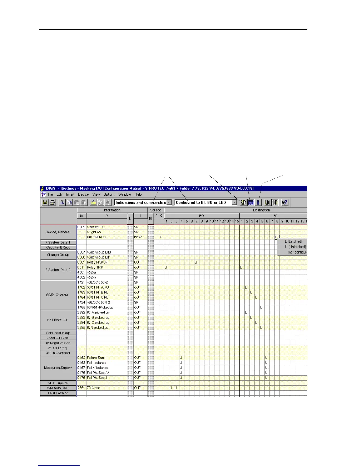
4 as a matrix (Figure 5-13). Each row is assigned to an information of the de-
vice. It is identified by a function number No, LCD text (display text D), an explanation
(long text L, minimized in Figure 5-13), and an information type T.Thecolumnsgive
the interfaces which should be the sources and/or destinations of the information. In
addition to physical device inputs and outputs, there may be internal interfaces for
user definable logic (CFC) (see also Section 5.3), message buffers, or the device dis-
play.
Figure 5-13 Extract from the configuration matrix in the DIGSI
®
4 user interface — example
Short viewStandard View
Information Catalog
Filter
 Loading...


