Functions
6-7
7SA6 Manual
C53000-G1176-C156-2
6.1.1 Power System Data 1
Some system and plant data are required by the device, so that it may adapt its func-
tions to these data, according to its mode of operation. Amongst others, the plant and
instrument transformer ratings, polarity and termination of the measured values, pa-
rameters of the circuit breaker, etc. These data are summarized in Power System
Data 1 (P.System Data 1).
If the key is operated, the main menu is displayed. With the key the option Set-
tings is selected and by pushing the key the selection of Settings is con-
firmed. To enter the plant data Power System Data 1 (P.System Data 1) must
be selected in the menu Settings.
With DIGSI
®
4 the corresponding selection is reached by double click on Settings.
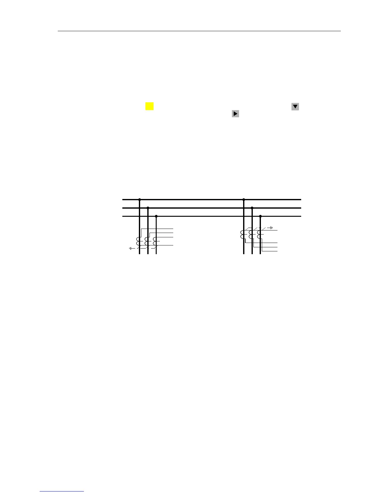
Polarity of Current
Transformers
In address 201 CT Starpoint the polarity of the current transformers must be en-
tered, in other words, the location of the CT star-point (Figure 6-8). This setting deter-
mines the measuring direction of the device (forward = line direction). A change of this
parameter also results in the polarity reversal of the earth current input.
Figure 6-8 Current transformer polarity
Instrument
Transformer
Nominal Values
In the address 203 Unom PRIMARY and 204 Unom SECONDARY thedeviceisin-
formed of the primary and secondary rated voltage (line voltage) of the voltage trans-
formers. In the address 205 CT PRIMARY and 206 CT SECONDARY the primary and
secondary rated current (phase current) of the current transformers are entered.
Please observe that the rated current transformer secondary current must corre-
sponds to the rated current of the device, as the device would otherwise compute in-
correct primary data.
Correct entry of the primary data is a prerequisite for the correct computation of oper-
ational measured values with primary magnitude. If DIGSI
®
4isusedtoenterparam-
eters as primary quantities, the correct entry of the primary data is an important pre-
requisite for the correct operation of the device.
Voltage
Transformer
Connection
The device contains four voltage measuring inputs, three of which are connected to
the set of voltage transformers. For the fourth voltage transformer U
4
input several op-
tions are available:
• Connection of the U
4
input to the open delta connection e–n of a set of voltage
transformers, refer also to Appendix A, Figures A-41 to A-45:
Address 210 is then set to: U4 transformer = Udelta transf..
MENU
I
L1
I
L2
I
L3
I
N
I
L1
I
L2
I
L3
I
N
Bus
Address 0201 =
towards Line
Line
Line
Address 0201 =
towards Busbar
 Loading...


