Installation and Commissioning
8-60 7SA6 Manual
C53000-G1176-C156-2
If the VT mcb is open the message “>FAIL:Bus VT ON” appears, if it is closed the
message “
>FAIL:Bus VT OFF” is displayed.
Switch off the protected power line.
8.3.8 Directional Checks with Load Current
Load Current
≥ 10 % I
N
The connections of the current and voltage transformers are checked using load cur-
rent on the protected line. The secondary load current must be at least 0.10 · I
N
.The
load current should be in-phase or lagging the voltage (resistive or resistive-inductive
load). The direction of the load current must be known. If there is a doubt, network
loops should be opened or other action taken to guarantee the direction of the load
current. The line remains energized during this directional test.
The direction can be derived directly from the operational measured values. Initially
the correlation of the measured load direction with the actual direction of load flow is
checked. In this case the normal situation is assumed whereby the forward direction
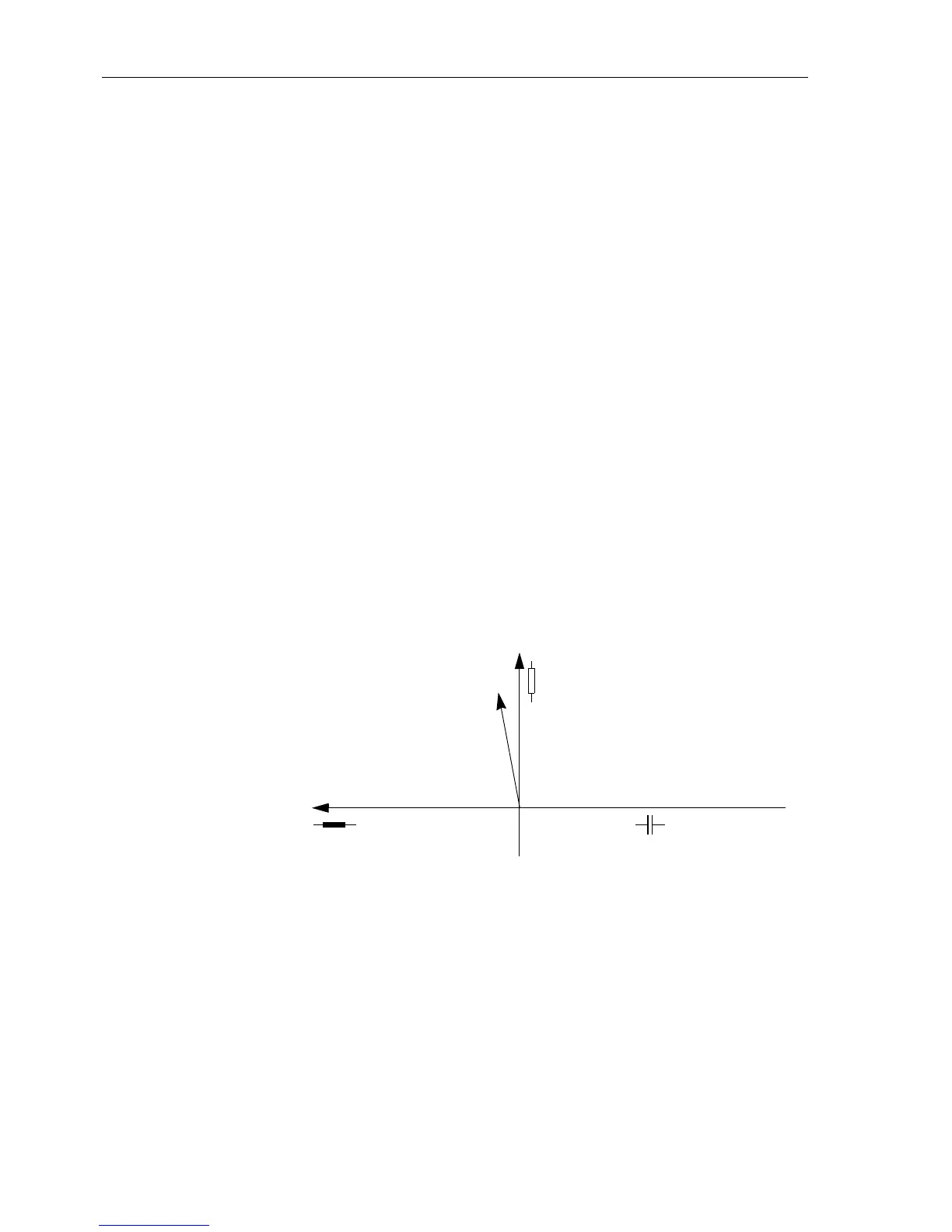
(measuring direction) extends from the busbar towards the line (Figure 8-30).
P positive, if active power flows into the line,
P negative, if active power flows towards the busbar,
Q positive, if reactive power flows into the line,
Q negative, if reactive power flows toward the busbar.
Figure 8-30 Complex (apparent) power
The power measurement provides an initial indication as to whether the measured val-
ues have the correct polarity. If both the active power as well as the reactive power
have the wrong sign, the polarity in address
201 CT Starpoint must be checked
and rectified.
The power measurement on its own is however not able to recognize all types of in-
correct connection. Accordingly, the impedances of all six measuring loops are eval-
uated. These can also be found as primary and secondaryquantitiesin the operational
measured values (Sub-section 7.1.3.1).
S
Load
P
jQ
Positive active power in
the direction of the line
Positive reactive power
in
the direction of the line
Negative reactive power
in
the direction of the line
 Loading...


