Functions
6-78 7SA6 Manual
C53000-G1176-C156-2
6.4 Protection Data Interfaces and Protection Data Topology (optional)
Where a teleprotection scheme is to be used to achieve 100% instantaneous protec-
tion, digital communication channels can be used for data transmission between the
devices. In addition to the protection data, other data can be transmitted and thus be
made available at the line ends. This data includes synchronization and topology data,
as well as remote trip signals, remote annunciation signals and measured values. The
topology of the protection data communication system is constituted by the allocation
of devices to the ends of the protected object and by the allocation of communication
paths to the protection data interfaces of the devices.
6.4.1 Function description
Communication
Topology
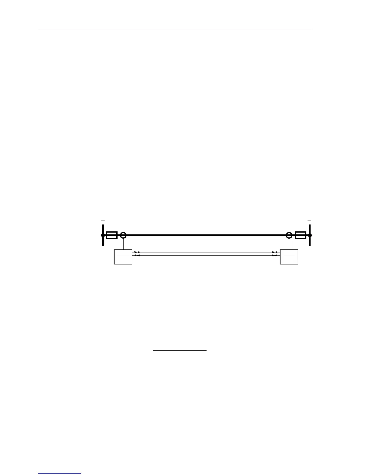
For a standard layout of lines with two ends, you require one protection data interface
for each device. The protection data interface is named PI 1 (see also Figure 6-44).
The corresponding protection data interface must have been set to
enabled during
configuration of the scope of functions.
Figure 6-44 Distance protection for two ends with two 7SA6 devices, each of them
having one protection data interface (transmitter/ receive
r)
Using three ends, at least one 7SA6 device with two protection data interfaces is re-
quired. Thus a communication chain can be formed. The number of devices (address
147 NUMBER OF RELAY) must correspond to the number of ends of the protected
object. Please observe that only current transformer sets that limit the protected object
are counted. The line in Figure 6-45, for instance, has
three ends and three devices.
It is limited by three current transformer sets. For this arrangement at least one
7SA522 with two protection data interfaces is required (communication chain).
Figure 6-45 shows a communication chain
with three devices.
The communication chain begins at protection data interface PI1 of device with index
1, continues in the device with index 2 at PI2, runs from device with index 2 from PI1
to the device with index 3 at PI1. The example shows that the indexing of the devices
must not necessarily have to correspond to the arrangement of the communication
chain. Which protection data interface is connected to which protection data interface
does not play a role.
PI1 or PI2
1 2
Index 1
PI1 or PI2
Index 2
7SA6 7SA6
 Loading...


