Functions
6-3037SA6 Manual
C53000-G1176-C156-2
Following each trip command the device registers the value of each phase current that
was switched off in each pole. This information is then provided in the trip log and ac-
cumulated in a register. The maximum current that was switched off is also stored.
If the device is equipped with the integrated automatic reclosure, the automatic close
commands are also counted, separately for reclosure after single-pole tripping, after
three-pole tripping as well as separately for the first reclosure cycle and other reclos-
ure cycles.
The counter and register contents are protected against loss of auxiliary voltage. They
may be set to zero or any other initial value. Further information can be obtained in
Subsection 7.1.2.
6.22.5 Circuit Breaker Trip Test
The Distance Protection 7SA6 allows for convenient testing of the trip circuits and the
circuit breaker.
The test programs as shown in Table 6-16 are available. The single-pole tests are nat-
urallyonlyavailableifthedeviceathandallowsforsingle-poletripping.Thelistedout-
put alarms must be allocated to the corresponding command relays, used for the op-
eration of the circuit breaker trip and close coils, during marshalling as stated in Sub-
section 5.2.3.
The test is initiated via the keypad and display on the front of the device or from a PC
with DIGSI
®
4. The procedure is described in Section 7.3. Figure 6-157 shows the se-
quence of a trip/close test cycle. The timer setting values are according to Sub-section
6.1.1 for “Trip/Close Command Duration” and “Circuit Breaker Test”.
If the auxiliary contacts of the circuit breaker or the individual circuit breaker poles in-
dicate the position of the circuit breaker via the binary inputs, the test cycle can only
be started when the circuit breaker is closed.
The information regarding the position of the circuit breaker is not automatically de-
rived from the position logic according to Sub-section 6.22.2 (Figure 6-151). For the
circuit breaker test function there are separate binary inputs for the switching status
feedback of the circuit breaker position. These must be taken into consideration when
allocating the binary inputs as mentioned in Section 6.22.2 (Page 294).
The alarms of the device show the respective state of the test sequence.
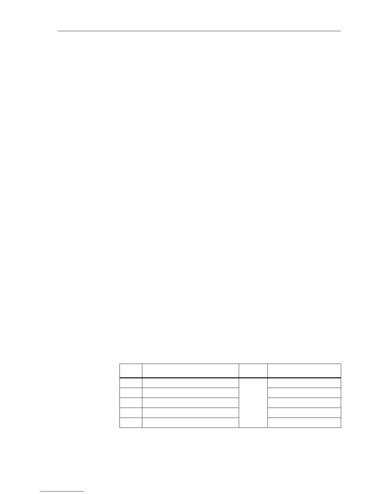
Table 6-16 Circuit breaker test programs
Seq.
No.
Test cycles CB Output alarm
1 1 pole TRIP/CLOSE cycle pole L1
CB 1
CB1-TESTtrip L1 (7325)
2 1pole TRIP/CLOSE cycle pole L2 CB1-TESTtrip L2 (7326)
3 1pole TRIP/CLOSE cycle pole L3 CB1-TESTtrip L3 (7327)
4 3pole TRIP/CLOSE cycle CB1-TESTtrip123 (7328)
applicable close command CB1-TEST close (7329)
 Loading...


