Functions
6-2
7SA6 Manual
C53000-G1176-C156-2
6.1 General
A few seconds after the device is switched on, the initial display appears in the LCD.
Depending on the device version either measured values (four-line display) or a sin-
gle-phase switching diagram of the feeder status (graphic display) is displayed in the
7SA6.
The setting parameters can be entered via the keypad and display on the front of the
device, or by means of a personal computer connected to the front or service interface
of the device utilising the DIGSI
®
4 software package. The level 5 password (individ-
ual parameters) is required.
From the
DeviceFront
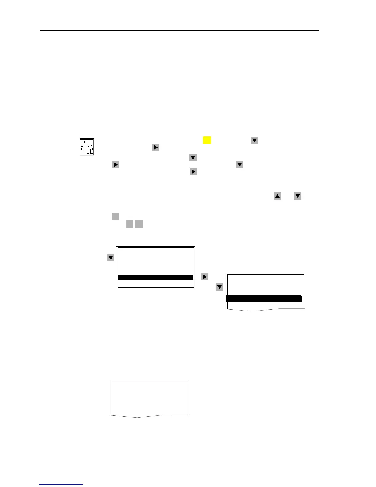
Select the MAIN MENU by pressing the key. Using the key, select Settings,
and then press the key to navigate to the SETTINGS display(seeFigure6-1).
In the SETTINGS display, use the key to select the desired function, and then use
the key to navigate to that function (e.g., use the key to select the P.System
Data1 function, and then use the key to navigate to the P.SYSTEM DATA1 dis-
play, as shown in Figure 6-2.
In general, an item number appears in the menu list to the right of each selection. Nav-
igation can be accomplished using the item number in place of the and keys.
This feature is particularly helpful in large menus (e.g., setting lists). Based on the ex-
ample above, from the MAIN MENU,theSETTINGS display can be reached by press-
ing on the keypad, and then the P.SYSTEM DATA1 display can be reached by
pressing on the keypad.
Figure 6-1 Example of navigation from the front control panel
Each setting contains a four-digit address number followed by the setting title as
shown in Figure 6-2. The value of the current setting is displayed in the line just below
the setting address number and title. The value may be text (Figure 6-2,
Address 0201) or numerical (Figure 6-2, Address 0202).
Figure 6-2 Example of power system data display
MENU
4
0 3
SETTINGS 03/11
---------------------
Device Config.–> 01
Masking (I/O) –> 02
P.System Data1–> 03
Group A –> 04
MAIN MENU 04/05
---------------------
Annunciation –> 1
Measurement –> 2
Control –> 3
Settings –> 4
Test/Diagnose –> 5
P.SYSTEM DATA1 01/16
---------------------
0201 CT Starpoint
towards Line
0202 Vnom PRIMARY
12.00kV
 Loading...


