Functions
6-144 7SA6 Manual
C53000-G1176-C156-2
6.8.1.2 Directional Unblocking Scheme
The following scheme is suited for conventional transmission media.
Principle The unblocking method is a permissive scheme. The difference to the Directional
Comparison Scheme (Sub-section 6.8.1.1) lies in that tripping is also possible when
no permissive signal from the opposite line end is received. Accordingly it is mainly
used on long lines where the signal is transmitted via the protected feeder by means
of power line carrier (PLC) and the attenuation in the signal transmission path at the
fault location can be so severe that reception of the signal from the opposite line end
cannot necessarily be guaranteed. A special unblock logic takes effect here.
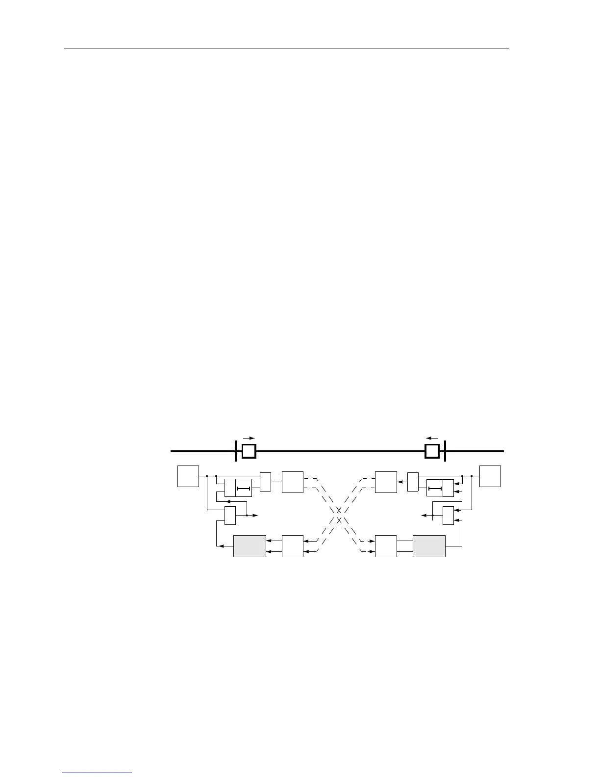
Figure 6-81 shows the operation scheme.
Two signal frequencies which are keyed by the transmit output of the 7SA6 are re-
quired for the transmission. If the transmission device has a channel monitoring, then
themonitoringfrequencyf
0
is keyed over to the working frequency (unblocking fre-
quency) f
U
. When the protection recognizes an earth fault in the forward direction, it
initiates the transmission of the unblock frequency f
U
. During the quiescent state or
during an earth fault in the reverse direction, the monitoring frequency f
0
is transmit-
ted.
If the unblock frequency f
U
is faultlessly received from the opposite end, a release sig-
nal is routed to the trip logic. A pre-condition for fast fault clearance is therefore that
the earth fault is recognized in the forward direction at both line ends.
The send signal can be prolonged by T
S
(parameter setting). The prolongation of the
sendsignalonlycomesintoeffectiftheprotectionhasalreadyissuedatripcommand.
This ensures that the permissivesignal releasesthe opposite line end even if the earth
fault is very rapidly cleared by a different independent protection.
Figure 6-81 Operation scheme of the directional unblocking method
Sequence Figure 6-82 shows the logic diagram of the unblocking scheme for one line end.
The directional unblocking scheme only functions for faults in the “forward” direction.
Accordingly the overcurrent stage intended for operation in the direction comparison
mode must definitely be set to
Forward (3I0... DIRECTION); refer also to Sub-
section 6.7.2 under the margin heading “Teleprotection with Earth Fault Protection”.
AB
T
S
&
trip
transm.
rec.
&
≥1
T
S
&
trip
transm.
rec.
&
≥1
f
U
f
U
f
0
f
0
unblock-
logic
unblock-
logic
UU
BB
f
0
– quiescent frequency (monit. frequency)
f
U
– unblocking frequency (send frequency)
U–unblocking signal
B–blocking signal
E/F.
frwd.
E/F.
frwd.
 Loading...


