Hardware and Connections
2-18
7SA6 Manual
C53000-G1176-C156-2
The following separation tool is needed to remove the contacts from the pin connec-
tors:
Type: 725840–1 from Messrs. Tyco Electronics AMP.
The separation tool contains a small tube that is subject to wear. The tube can be or-
dered separately:
Type: 725841–1 from Messrs. Tyco Electronics AMP.
2.1.4 Connections to Optical Communication Interfaces
Optical Interfaces
ST–Connectors
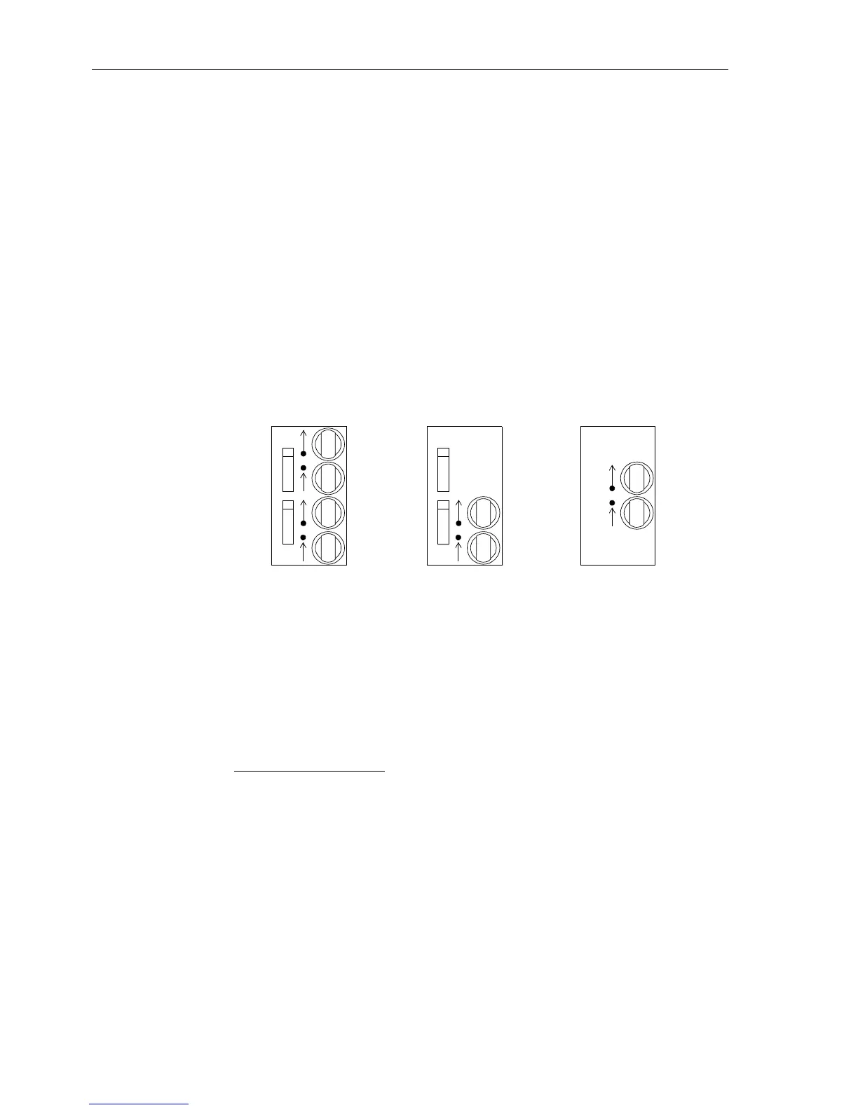
The three available versions of optical communication interfaces are shown in Figure
2-18. The ports are supplied with caps to protect the optical components against dust
or other contaminants. The caps can be removed by turning them 90° to the left.
Figure 2-18 Optical communication interfaces with protective caps
Connections to
Optical
Communication
Interfaces with
ST–Connectors
Optical connector type: ST–connector
Fibre type: Multimode graded-index (“G”) optical fibre
G50/125 µm,
G62.5/125 µm,
G100/140 µm
Wavelength: λ = 820 nm (approximately)
Allowable bending radius:
For indoor cable r
min
=5cm(2in)
Foroutdoorcable r
min
=20cm(8in)
Laser class 1 (acc. EN 60825–1) is achieved with fibre type G50/125 µm and
G62.5/125 µm.
Connections to
Optical
Communication
Interfaces with
FC–Connectors
The optical communication interfaces with FC-connectors and screw connections also
provide caps to protect the optical components against dust or other contaminants.
2 channel 1 channel
Ch1
P-Slave
Ch2
P-Master
UART
Ch1
P-Slave AMO
1 channel
 Loading...


