Functions
6-146 7SA6 Manual
C53000-G1176-C156-2
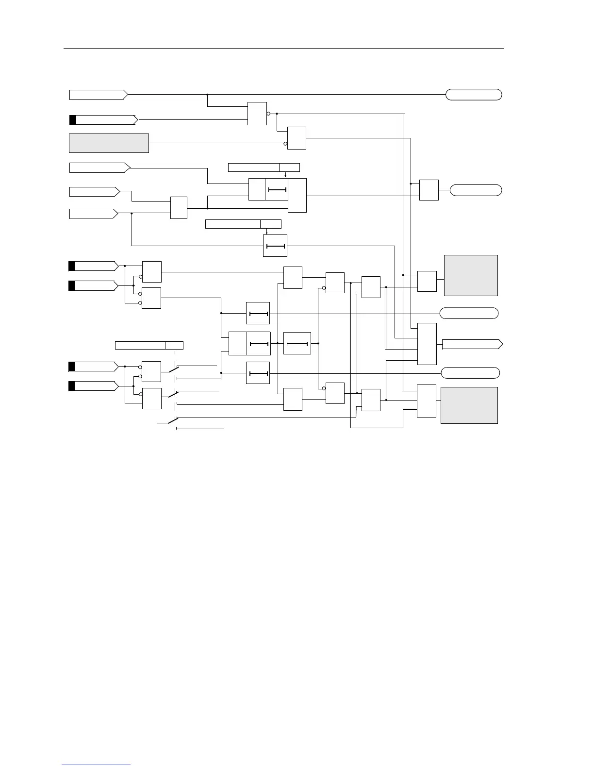
Figure 6-82 Logic diagram of the unblocking scheme (one line end)
6.8.1.3 Directional Blocking Scheme
The following scheme is suited for conventional transmission media.
Principle In the case of the blocking scheme, the transmission channel is used to send a block
signal from one line end to the other. The signal transmission is started as soon as a
fault in reverse direction is detected, optionally also right after fault inception (jump de-
tector via dashed line). It is stopped as soon as the earth fault protection detects a fault
in forward direction, alternatively the signal is only sent when the earth fault protection
detects the fault in the reverse direction. On the other hand the signal will be main-
tained if the fault is in reverse direction. If the signal is sent with jump detections (i. e.
1390 EF Tele BL Jump is routed in parallel with 1384 EF Tele SEND), only a short
delay to allow for signal transmission is required before the directional E/F trips. Trip-
ping is possible with this scheme even if no signal is received from the opposite line
end. It is therefore mainly used for long lines when the signal must be transmitted
across the protected feeder by means of power line carrier (PLC) and the attenuation
of the transmitted signal at the fault location may be so severe that reception at the
other line cannot necessarily be guaranteed.
EF Telep. off
>EF TeleprotBLK
EF Pickup
&
EF forwards
3203Send Prolong.
T0
&
EF Enable TripS
≥1
Trip command
&
Transient blocking
&
EF Tele SEND
EF Telep. OFF
≥1
&
Echo function
section 6.8.1.5
≥1
100100020
ms ms
>EF UB bl 1
>EF UB ub 12
>EF UB ub 1
>EF UB bl 2
&
&
&
&
Two terminals
Three terminals
Two terminals
Three terminals
„1“
3202Line Config.
Two terminals
Three terminals
≥1
≥1
&
&
≥1
≥1
010
s
EF TeleUB Fail1
010
s
EF TeleUB Fail2
FNo 1313
FNo 1320
FNo 1321
FNo 1322
FNo 1323
FNo 1381
FNo 1384
FNo 1387
FNo 1388
Week-Infeed
tripping
acc. Fig. 6-89
&
&
3208Release Delay
T0
 Loading...


