Introduction
1-2
7SA6 Manual
C53000-G1176-C156-2
1.1 Overall Operation
The numerical Distance Protection SIPROTEC
®
7SA6 is equipped with a powerful 32
Bit microprocessor. This provides fully numerical processing of all functions in the
device, from the acquisition of the measured values up to the output of commands to
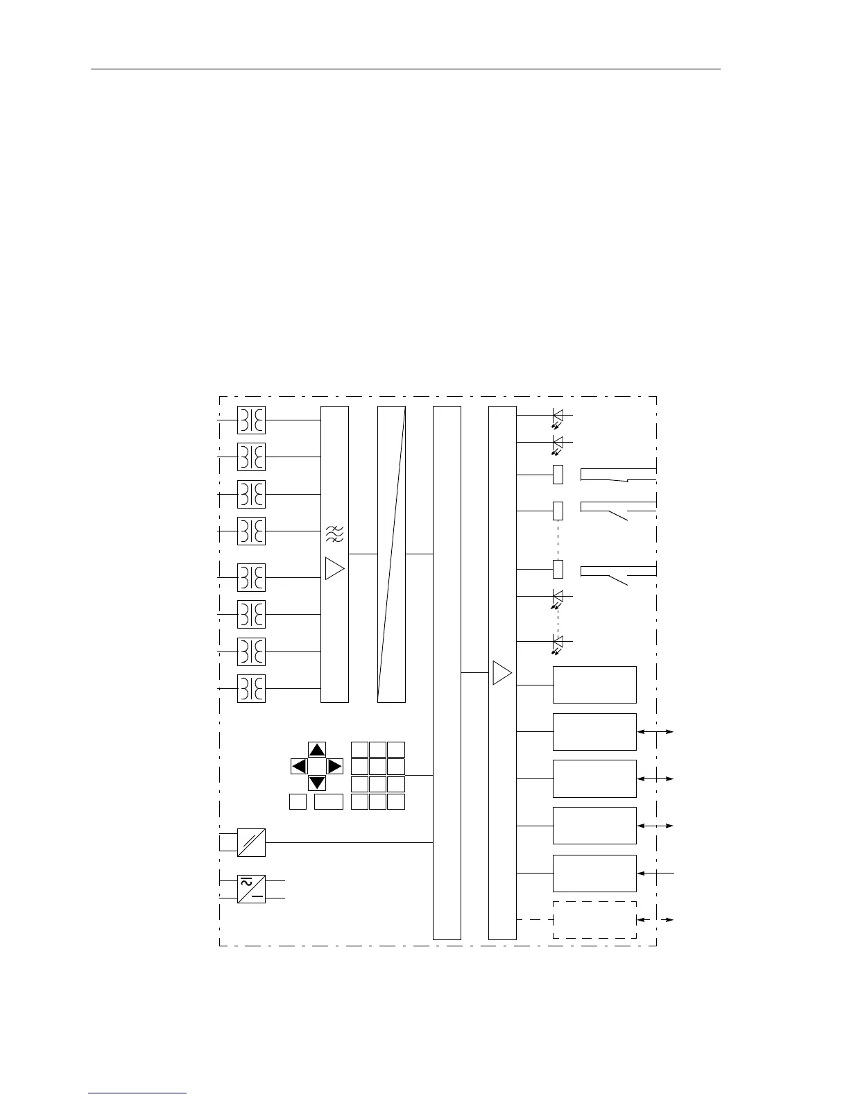
the circuit breakers. Figure 1-1 shows the basic configuration of the device.
Analog Inputs The measuring inputs MI transform the currents and voltages derived from the
instrument transformers and match them to the internal signal levels for processing in
the device. The device has 4 current and 4 voltage inputs. Three current inputs are
provided for measurement of the phase currents, a further measuring input (I
4
)may
be configured to measure the earth current (residual current from the current
transformer star-point), the earth current of a parallel line (for parallel line
compensation) or the star-point current of a power transformer (for earth fault direction
determination).
µC
∩
#
Error
Run
Output Relays
(allocatable)
LEDs
on the
Front Panel
(allocatable)
Display on
the Front Panel
Operating
Interface
to
PC
System
Interface
to
SCADA
I
L1
I
L2
I
L3
I
4
U
L1
U
L2
U
L3
U
4
789
456
123
.
0+/-
ESC
ENTER
Operator
Control Panel
aux
Binary Inputs (allocatable)
Power Supply
Time
Synchronization
MI IA AD µC OA
Figure 1-1 Hardware structure of the numerical device 7SA6 (maximum configuration)
e.g.
CF77
IRIGB
PS
Service
Interface
PC/
Modem
„Fault“
Protection Data
Interface
to
remote
end/CC
 Loading...


