Routine Checks and Maintenance
9-97SA6 Manual
C53000-G1176-C156-2
9.4 Troubleshooting
If a device reports a problem or failure, the procedure below is recommended.
If none of the LEDs on the front panel are lit, then verify:
o Are the printed circuit boards put into the correct slots and properly covered by the
front panel?
o Are the plug connectors of the flat cable plugged into the printed circuit boards and do
the lockings snap properly?
o Is the auxiliary voltage high enough? Is the polarity at the corresponding connections
correct?
o Are the voltage magnitude and polarity correct for the power supply. Connection draw-
ings are shown in Section A.2 of Appendix A?
o Has the fuse in the power supply not blown? The location of the fuse is shown in Fig-
ure 9-7. If the fuse needs to be replaced, see Subsection 9.5.2.
If the red “ERROR” LED is on and the green “RUN” LED is off, then the device has
recognized an internal fault. Re-initializing the device can be attempted, see Section
9.2.
If you see the following display, the device has arrived “monitor”-mode. In this case
you may initialize the device via DIGSI
®
4:
Figure 9-3 Monitor annunciation in device display
G Connect the operating interface of the SIPROTEC
®
4devicewiththeoperatingin-
terface of the SIPROTEC
®
4 device and open the DIGSI
®
4softwareprogram.
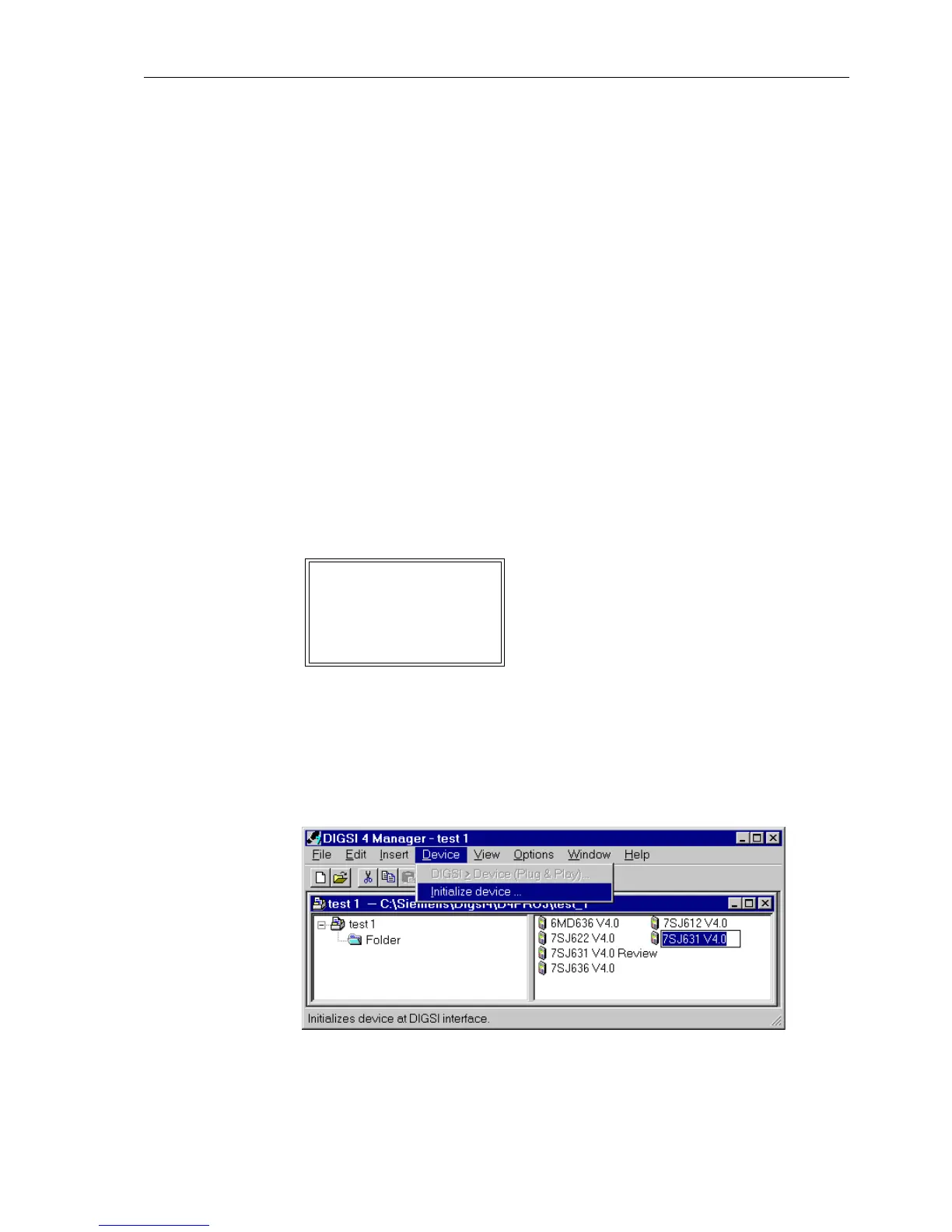
G Select Initialize device in the menu Device (Figure 9-4).
Figure 9-4 Initializing device via DIGSI
®
4
MONITOR 01/05
---------------------
Equipment data –> 1
User interface –> 2
System I-face –> 3
Reset –> 4
Siemens insten –> 5
 Loading...


