Functions
6-308 7SA6 Manual
C53000-G1176-C156-2
6.23.2 Operational Measurement
Display of
Measured Values
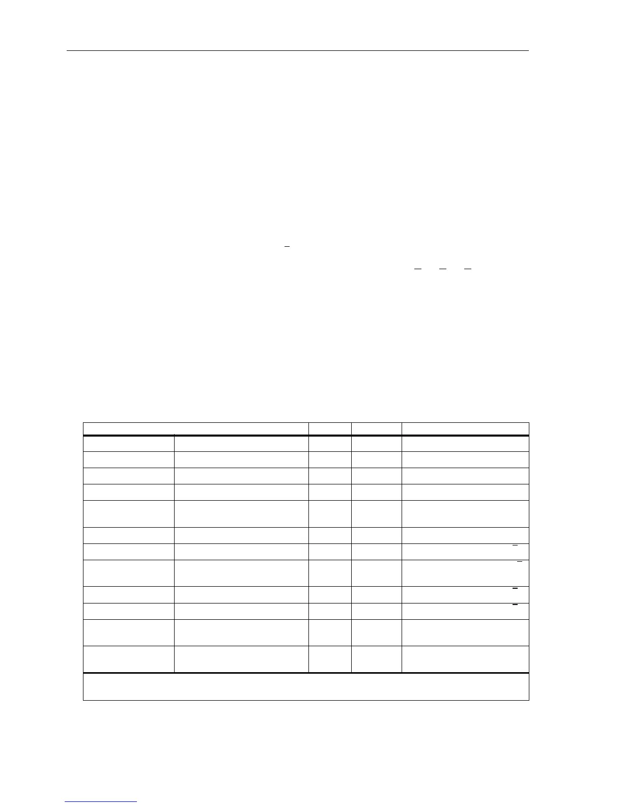
A range of measured values and values derived from these are available continuously
forlocaldisplayordatatransfer(refertoTable6-17).
A precondition for the correct display of primary and percentage values is the com-
plete and correct entry of the instrument transformer and plant rated values, as well
as the transformation ratios of the current and voltage transformers in the earth con-
nections according to Sub-section 6.1.1.
Depending on the ordering code and the manner of connection to the device, only a
portion of the listed operational measured values in Table 6-17 may be available. Of
the current values I
EE
,I
Y
und I
P
only the one which is connected to the current meas-
uring input I
4
can apply. The phase-earth voltages can be measured if the voltage in-
puts phase-earth are connected. The displacement voltage 3U
0
is the e–n voltage
U
en
, usually multiplied by √3 (setting address 211, Uph / Udelta)—ifU
en
is con-
nected — or derived from the phase–earth voltages 3U
0
=|U
L1
+U
L2
+U
L3
|. The three
phase–earth voltage inputs must be connected for this.
For the thermal overload protection the calculated overtemperatures are indicated in
relation to the trip overtemperature.
If the device is provided with the synchronism and voltage check, the characteristic
values (voltages, frequencies, differences) can be read out.
If the device is provided with the earth fault detection function for non-earthed sys-
tems, the components of the earth current (active and reactive component) are indi-
cated, as well.
Table 6-17 Operational measured values
Measured values primary secondary % referred to
I
L1
,I
L2
,I
L3
phase currents A A rated operational current
1
)
3I
0
earth currents A A rated operational current
1
)
I
1
,I
2
pos. and neg. seq. currents A A rated operational current
1
)
3I0
sen
sensitive earth current A mA rated operational current
1
)
3
)
I
Y
,I
P
transformer star point current or
earth current in the parallel line
A A rated operational current
1
)
3
)
U
L1–L2
,U
L2–L3
,U
L3–L1
line voltages kV V rated operational voltage
2
)
U
L1–E
,U
L2–E
,U
L3–E
phase-earth voltages kV V rated operational voltage /√3
2
)
3U
0
displacement voltage kV V rated operational voltage ·√3
2
)
4
)
U
X
voltage at the measuring input U
4
kV V rated operational voltage /√3
2
)
U
1
,U
2
pos. and neg. seq. voltages kV V rated operational voltage /√3
2
)
R
L1–E
,R
L2–E
,R
L3–E
R
L1–L2
,R
L1–L2
,R
L3–L1
operational resistances
of all conductor loops
ΩΩ —
X
L1–E
,X
L2–E
,X
L3–E
X
L1–L2
,X
L2–L3
,X
L3–L1
operational reactances
of all conductor loops
ΩΩ —
1
) acc. to address 1104 (refer to Sub-section 6.1.3)
2
) acc. to address 1103 (refer to Sub-section 6.1.3)
3
) with consideration of the factor 221 I4/Iph CT (refer to Sub-section 6.1.1)
 Loading...


