Functions
6-288 7SA6 Manual
C53000-G1176-C156-2
Note that the fast trip of Zone 1 is delayed by the setting in 2921. Unless absolutely
necessary the setting should be zero. Alternatively the internal Fuse Failure Monitor
canbeused(seeabove).
Trip Circuit
Supervision
The number of circuits to be monitored was set during the configuration in address
140 TripCirc.Superv (Section 5.1). If the trip circuit supervision is not used at all,
the setting
Disabled must be applied there.
The trip circuit supervision can be switched
ON or OFF in address 4001 FCT Trip-
Superv.
. The number of binary inputs that shall be used in each of the monitored cir-
cuits is set in address
4002 No. of BI. If the marshalling of the binary inputs re-
quired for this function does not correspond to the previously selected type of monitor-
ing, a corresponding alarm is issued (“
TripC ProgFAIL” with the number of the
faulty monitoring circuit).
The trip circuit failure alarm is delayed by a fixed period of approximately 1 s to 2 s in
the case of monitoring with two binary inputs. The alarm delay in the event of monitor-
ing with one binary input can be set in address
4003 Alarm Delay.If7SA6isthe
only device connected in the trip circuit, a delay of 1 s to 2 s is sufficient as the trip
circuit supervision is not active during a detected system fault. If, however, trip con-
tacts from other devices are connected in parallel in the trip circuit, the fail alarm must
be delayed such that the longest trip command duration can be reliably bridged.
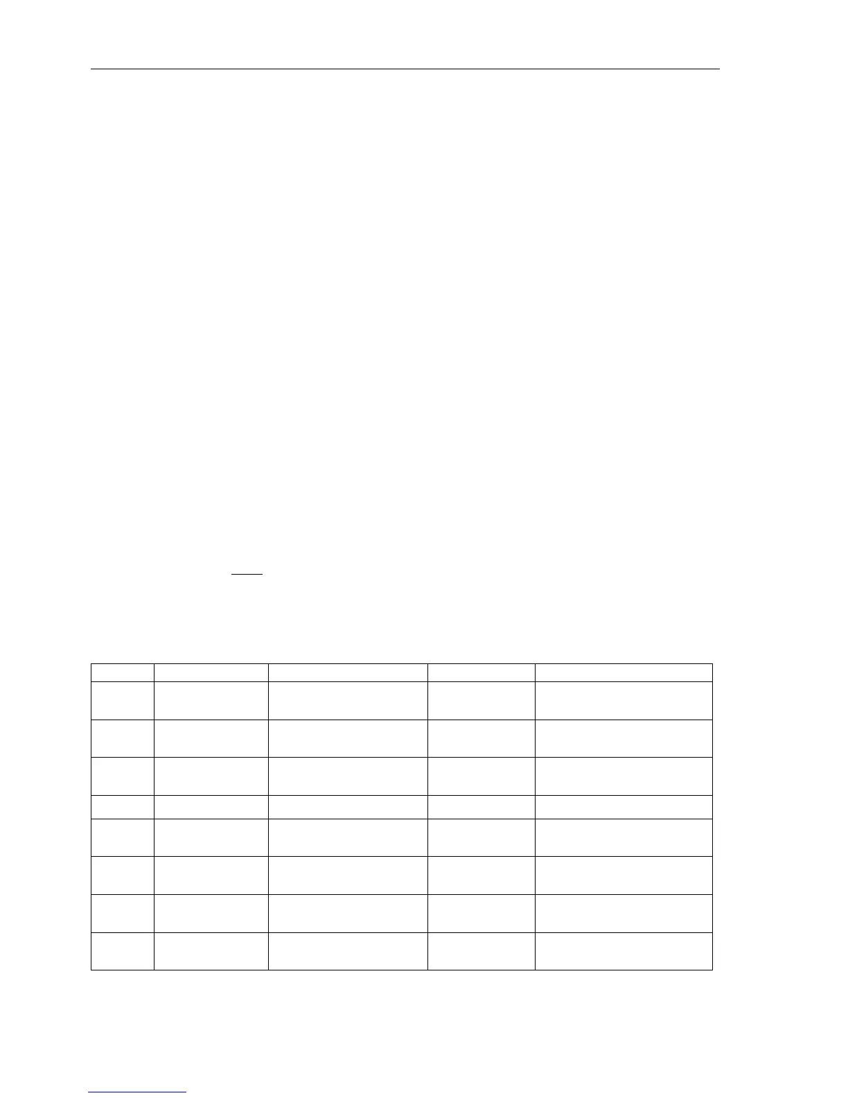
6.21.3 Settings
Measurement
Supervision
Note: The indicated secondary current values for setting ranges and default settings
refer to I
N
= 1 A. For the nominal current 5 A the current values are to be multiplied
by 5. The values of impedance are divided by 5.
Addresses which have an „A“ attached to its end can only be changed with DIGSI
®
4
in “
Additional Settings“.
Addr. Setting Title Setting Options Default Setting Comments
2901 MEASURE.
SUPERV
ON
OFF
ON Measurement Supervision
2902A BALANCE U-LIMIT 10..100 V 50 V Voltage Threshold for Balance
Monitoring
2903A BAL. FACTOR U 0.58..0.95 0.75 Balance Factor for Voltage
Monitor
2904A BALANCE I LIMIT 0.10..1.00 A 0.50 A Current Balance Monitor
2905A BAL. FACTOR I 0.10..0.95 0.50 Balance Factor for Current Moni-
tor
2906A ΣI THRESHOLD 0.05..2.00 A 0.10 A Summated Current Monitoring
Threshold
2907A ΣI FACTOR 0.00..0.95 0.10 Summated Current Monitoring
Factor
2910 FUSE FAIL MON. ON
OFF
ON Fuse Failure Monitor
 Loading...


