Installation and Commissioning
8-68 7SA6 Manual
C53000-G1176-C156-2
8.3.12 Measuring the operating time of the circuit breaker
Only for
Synchronism
Check
If the device is equipped with the function for synchronism and voltage check and it is
applied, it is necessary — under asynchronous system conditions — that the operat-
ing time of the circuit breaker is measured and set correctly when closing. If the syn-
chronism check function is not used or only for closing under synchronous system
conditions, this subsection is irrelevant.
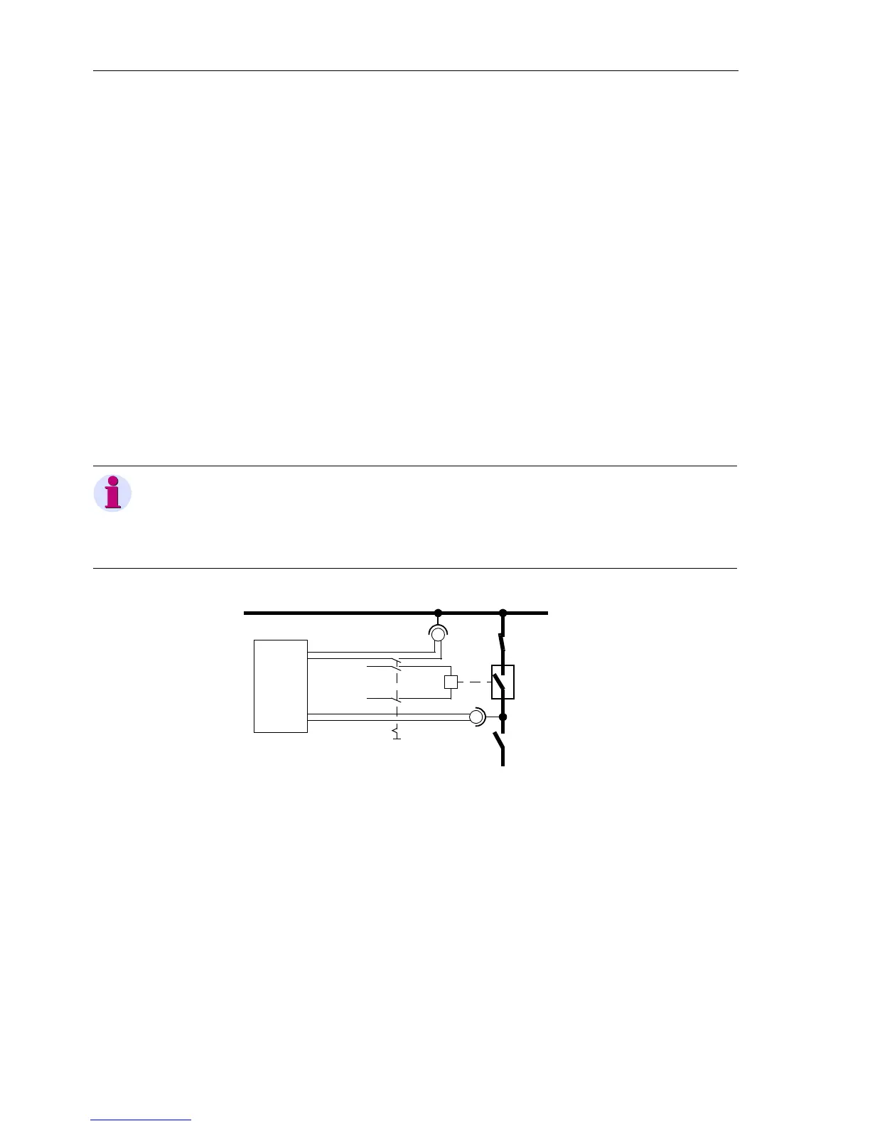
For measuring the operating time a setup as shown in figure 8-35 is recommended.
The timer is set to 1 s and a graduation of 1 ms.
The circuit breaker is closed manually. At the same time the timer is started. After clos-
ing the poles of the circuit breaker, the voltage U
Line
appears and the timer is stopped.
The time displayed by the timer is the real circuit breaker closing time.
If the timer is not stopped due to an unfavourable closing moment, the attempt will be
repeated.
It is particularly favourable to calculate the mean from several (3 to 5) successful
switching attempts.
Set the calculated time under address
239 as T-CB close (under power system data
2). Select the next lower adjustable value.
Figure 8-35 Measuring the circuit breaker closing time
Note:
The operating time of the accelerated output relays for command tripping is taken into
considerationbythedeviceitself.Thetrippingcommandistobeallocatedtoasuch
relay. If this is not the case, then add 3 ms to the measured circuit-breaker operating
time for achieving a greater reaction time of the “normal” output relay.
Busbar
U
Line
Feeder
Busbar
L+
L–
Timer
Start
Stop
Close
Voltage
 Loading...


